GB-14
Valve housing: aluminium,
valve seal: NBR.
Connection flanges:
VAS/VCS 1 – 3 with internal thread:
Rp pursuant to ISO 7-1, NPT pursuant to ANSI/
ASME;
VAS/VCS of size 2 and higher: with PN16ISO
flange (pursuant to ISO 7005), with ANSI flange
pursuant to ANSI 150.
Electrical data
Cable gland: M20 x 1.5.
Electrical connection: cable with max. 2.5mm
2
(AWG12) or plug with socket to EN175301-803.
Duty cycle: 100%.
Power factor of the solenoid coil: cosφ=0.9.
Mains voltage:
230 V AC, +10/-15%, 50/60 Hz;
200 V AC, +10/-15%, 50/60 Hz;
120 V AC, +10/-15%, 50/60 Hz;
100 V AC, +10/-15%, 50/60 Hz;
24 VDC, ±20%.
Power consumption:
Type Voltage Power
VAS 1
24 V DC 25 W –
100 V AC 25 W (26 VA)
120 V AC 25 W (26 VA)
200 V AC 25 W (26 VA)
230 V AC 25 W (26 VA)
VAS 2, VAS 3
24 V DC 36 W –
100 V AC 36 W (40 VA)
120 V AC 40 W (44 VA)
200 V AC 40 W (44 VA)
230 V AC 40 W (44 VA)
VBY
24 V DC 8 W –
120 V AC 8 W –
230 V AC 9.5 W –
Contact rating of proof of closure switch:
Type Voltage
Min. current
(resistive
load)
Max. cur-
rent (resis-
tive load)
VAS..S
12 – 250VAC,
50/60 Hz
100 mA 3 A
VAS..G 12 – 30VDC 2 mA 0.1 A
Switching frequency of proof of closure switch:
max. 5 x per minute.
Switching
current [A]
Switching cycles*
cos φ = 1 cos φ = 0.6
0.1 500,000 500,000
0.5 300,000 250,000
1 200,000 100,000
3 100,000 –
* Limited to max. 200,000 cycles for heating
systems.
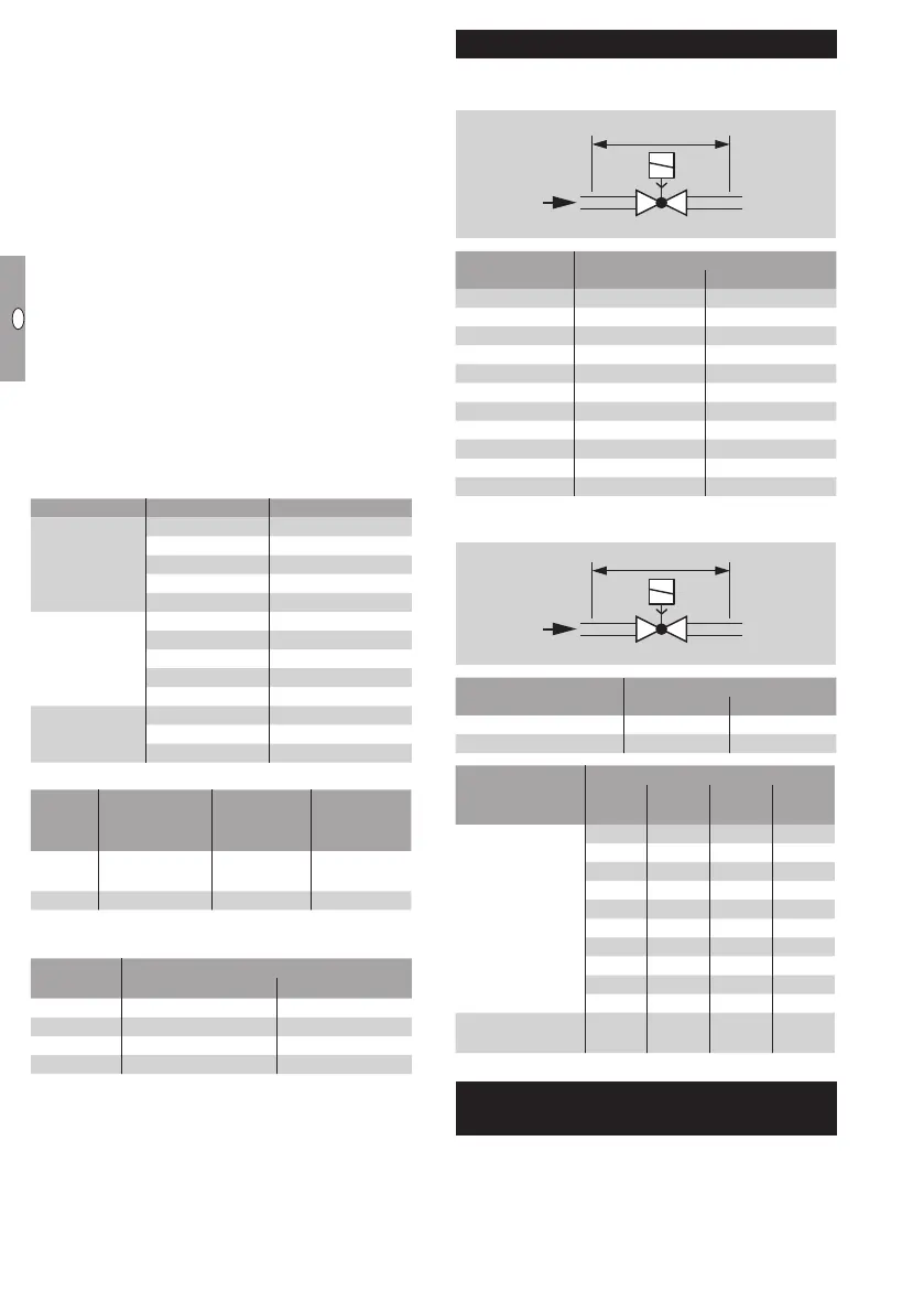
Air flow rate Q
Air flow rate Q for a pressure loss of ∆p= 1mbar
(0.4"WC)
∆p 1 mbar (0,4 "WC)
1 x VAS
∆p 10 mbar (4 "WC)
1 x VBY/1 x VAS 1
Type
Air flow rate
Q [m
3
/h] Q [SCFH]
VAS 110 4.4 155.4
VAS 115 5.6 197.7
VAS 120 8.4 296.6
VAS 125 9.5 335.5
VAS 225 16.7 589.7
VAS 232 21 741.5
VAS 240 23.2 819.2
VAS 250 23.7 836.8
VAS 340 33.6 1186.4
VAS 350 36.4 1285.3
VAS 365 37.9 1338.2
Air flow rate Q for a pressure loss of ∆p= 10mbar
4"WC)
∆p 1 mbar (0,4 "WC)
1 x VAS
∆p 10 mbar (4 "WC)
1 x VBY/1 x VAS 1
Type
Air flow rate
Q [m
3
/h] Q [SCFH]
Bypass valve VBY 0.85 30.01
Pilot gas valve VBY 0.89 31.43
Type
Air flow rate
Ø [mm]
Q
[m
3
/h]
Ø ["]
Q
[SCFH]
Bypass valve
VAS 1
1 0.2 0.04 7.8
2 0.5 0.08 17.7
3 0.8 0.12 28.2
4 1.5 0.16 53.1
5 2.3 0.20 81.2
6 3.1 0.24 109.5
7 3.9 0.28 137.7
8 5.1 0.31 180.1
9 6.2 0.35 218.9
10 7.2 0.39 254.2
Pilot gas valve
VAS 1
10 8.4 0.39 296.6
Safety information in accordance
with EN61508-
See Technical Information VAS, VCS (D, GB, F) –
www.docuthek.com
 Loading...