GB-6
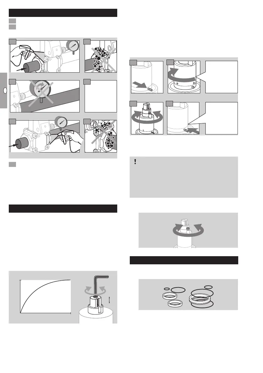
Tightness test
1 Close the gas solenoid valve.
To be able to check the tightness, shut off the
downstream pipeline close to the valve.
N
2
0
0
N
2
3
6
4
7
8
5
0
≤ 1,5 × p
u max
≤ 1,5 × p
u max
Open the
solenoid
valve.
9 Tightness OK: open the pipeline.
▷
Pipeline leaking: replace O-ring on flange, see
accessories, seal set for sizes 1 – 3. Then check
for tightness once again.
▷ Unit leaking: remove the unit and return it to the
manufacturer.
Commissioning
Setting the flow rate
▷
At the factory, the gas solenoid valve is adjusted
for maximum flow rateQ.
▷ The markings on the cover cap can be used for
coarse adjustment of the flow rate.
▷ The cover cap can be rotated without changing
the current flow rate.
▷ Allen key: 2.5 mm.
▷ Do not turn beyond the “max.” setting.
Q [%]
max.
min.
100
0
U
-
+
min.
max.
▷
The VAS remains tight even if the adjusting screw
is overturned.
Setting the start gas rate on VAS../L, VCS..L
▷
The start gas rate can be set by turning the
damping unit a maximum of 5turns.
▷ There must be a period of 20 seconds between
switching the valve off and on again so that the
damping is fully effective.
▷
Loosen the M5 setscrew (2.5 mm hexagon
socket), but do not unscrew completely.
3 4
1
2
Turn
clockwise
to the zero
setting/as far
as possible.
Screw the M5
in.
Setting the damping speed
▷
The opening speed can be influenced by turning
the nozzle screw on the damping unit.
CAUTION
Attention! To avoid leakage, please observe the
following:
– If the nozzle screw is turned by more than 1turn,
the damping unit will leak and will have to be
replaced.
▷ Turn the nozzle screw a maximum of ½ a turn in
the appropriate direction.
-
Replacing the actuator
▷ The actuator adapter set is enclosed with new
actuators.
VAS 2/3VAS 1
▷
The seals of the actuator adapter set are covered with
a non-stick coating. No additional grease is required.
 Loading...