GB-9
Accessories
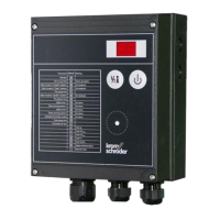
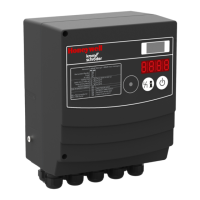
Pressure switch for gas DG..VC
▷
The pressure switch for gas monitors the inlet
pressurep
u
, the outlet pressurep
d
and the in-
terspace pressurep
z
.
p
p
d
▷
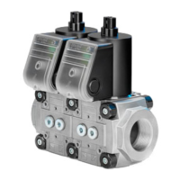
When using two pressure switches on the same
side of the double solenoid valve, only the com-
bination DG..C..1 and DG..C..9 may be used for
design reasons.
DG..C..1
DG..C..9
p
u
p
z
▷
When retrofitting the pressure switch for gas,
see enclosed operating instructions “Pressure
switches for gas DG..C”, section entitled “Mount-
ing the DG..C..1, DG..C..9 on valVario gas so-
lenoid valves”.
▷
The switching point is adjustable via hand wheel.
Adjusting range
(adjusting tolerance
= ± 15% of the
scale value)
Mean switching
differential at min.
and max. setting
[mbar] ["WC] [mbar] ["WC]
DG 17VC 2 – 17 0.8 – 6.8
0.7 – 1.7
0.3 – 0.8
DG 40VC 5 – 40 2 – 16 1 – 2 0.4 – 1
DG 110VC 30 – 110 12 – 44 3 – 8 0.8 – 3.2
DG 300VC
100 – 300
40 – 120 6 – 15 2.4 – 8
▷
Deviation from the switching point during testing
pursuant to EN 1854 Gas pressure switches:
± 15%.
Bypass/pilot gas valves
1 Disconnect the system from the electrical power
supply.
Shut off the gas supply.
Prepare the installed main valve.
▷ Turn the actuator so that the side on which the
bypass/pilot gas valve is to be installed is ac-
cessible.
65
4
VBY for VAS 1
Medium and ambient temperatures: 0 to +60°C
(32 to 140°F), no condensation permitted.
Enclosure: IP 54.
Scope of delivery
B
C
A
VBY 8
VAS 1
Bypass valve VBY..I
A 1 x bypass valve VBY..I
B 2 x retaining screws with 4 x O-rings: both retain-
ing screws have a bypass orifice
C Grease for O-rings
▷ The screw plug at the outlet remains in place.
Pilot gas valve VBY..R
A 1 x pilot gas valve VBY..R
B 2 x retaining screws with 5 x O-rings: one retain-
ing screw has a bypass orifice (2x O-rings), the
other does not (3x O-rings)
C Grease for O-rings
▷
Remove the screw plug at the outlet and connect
the Rp¼ pilot gas line.
Mounting the VBY
7 Grease O-rings B.
VBY..I
VBY..R
8
9
10
11
▷ Tighten the retaining screws alternately so that
VBY and VAS are flush.
 Loading...