GB-10
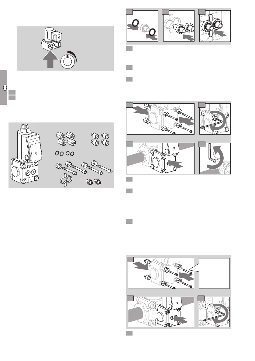
Setting the flow rate
▷ The flow rate can be set by turning the flow rate
restrictor (4mm hexagon socket) ¼ of a turn.
+
-
▷
Only adjust the flow rate restrictor in the marked
range, otherwise the required gas volume will
not be reached.
1 Wire the socket, see page4 (Wiring).
1 Check for tightness, see accessories, checking
the bypass/pilot gas valve for tightness.
VAS 1 for VAS 1, VAS , VAS
Scope of delivery
A
B
C
VAS 1VAS 2/3
D
F
E
C
A 1 x bypass/pilot gas valve VAS1
B 4 x O-rings
C 4 x double nuts for mounting to VAS1
or
4 x spacer sleeves for mounting to VAS2/3
D 4 x connection parts
E 1 x mounting aid
Bypass valve VAS 1
F 2 x connection pipes, if the bypass valve has a
blind flange on the outlet side
Pilot gas valve VAS 1
F 1 x connection pipe, 1 x sealing plug, if the pilot
gas valve has a threaded flange on the outlet
side
Mounting the bypass/pilot gas valve VAS1
▷
Always use a connection pipeF at the inlet of
the main valve.
▷
For a bypass valve: use connection pipeF
Ø10mm(0.39") at the outlet of the main valve
if the bypass valve’s outlet flange is designed
as a blind flange.
▷ For the pilot gas valve: insert sealing plugF at
the outlet of the main valve if the pilot gas valve’s
outlet flange is designed as a threaded flange.
E
F
B
B
8
9
7
10 Remove the sealing plugs on the mounting side
of the bypass valve.
VAS 1 to VAS 1
11 Remove the nuts from the connection parts on
the mounting side of the main valve.
1 Remove the connection parts of the bypass/pilot
gas valve.
▷
Use the new connection parts C and D from the
scope of delivery for the bypass/pilot gas valve.
C
D
13
14
15
16
17 Wire the bypass/pilot gas valve VAS1, see
page4 (Wiring).
18 Check for tightness, see accessories, checking
the bypass/pilot gas valve for tightness.
VAS 1 for VAS or VAS
▷ The connection parts of the main valve remain
mounted.
11 Remove the connection parts of the bypass/pilot
gas valve.
▷
Use the new connection parts C and D from
the scope of delivery for the bypass/pilot gas
valve. For VAS2 and VAS3, the connection
parts consist of self-tapping screws.
C
D
12
13
14
Self-tapping
screws.
15 Wire the bypass/pilot gas valve VAS1, see
page4 (Wiring).
 Loading...