1 Supplementary Operating Manual
7 of 12
Double Mechanical Seals
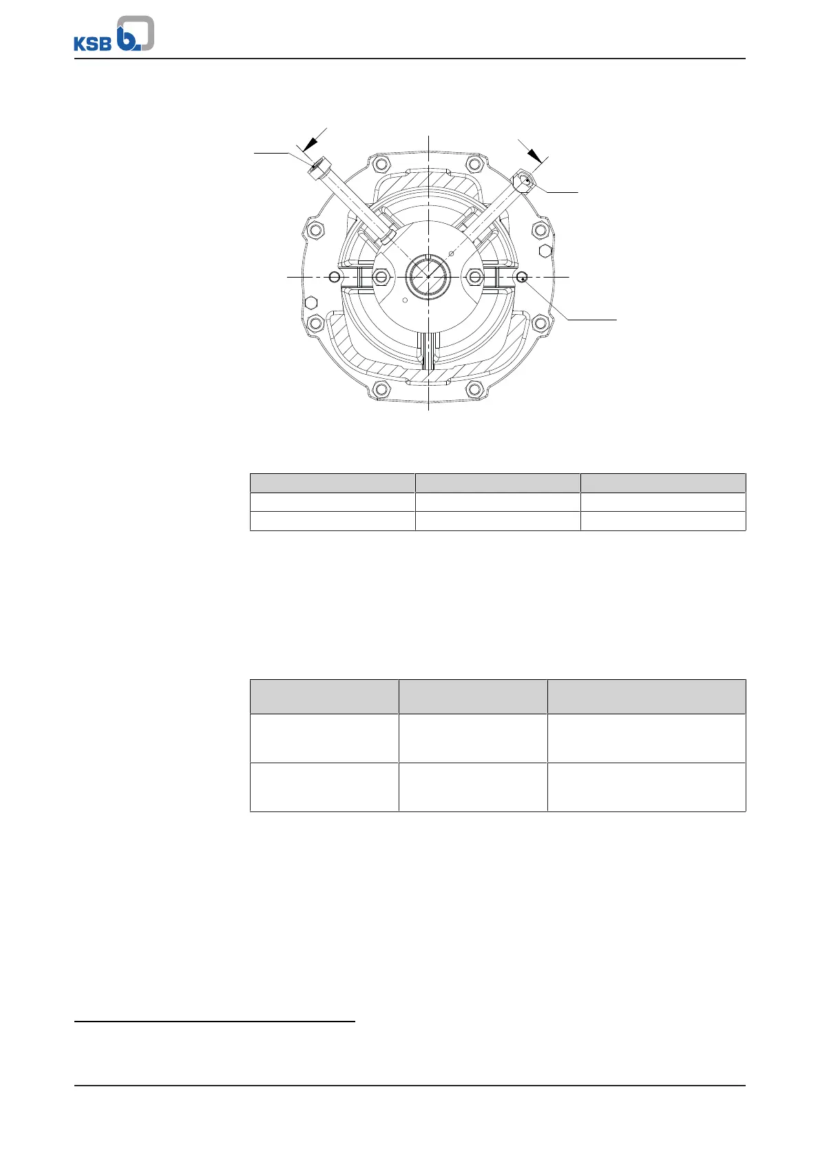
1.5.2 Connections
10A
10E
901.98
550.74
A
A
UG1385256-D01_002
Fig.2: Connections of seal supply system
Table5: Connections
Connection
2)
Description Size
3)
10A Barrier fluid outlet G 1/4
10E Barrier fluid inlet G 1/4
1.5.3 Requirements to be met by the seal supply system
Pipework routing
requirements
When routing pipework and flexible tubing, prevent any high points or ensure that
high points can be vented separately to prevent dry running of the mechanical seal.
The connecting pipes between the main pipe and the pump must be routed with a
continuously rising slope to assure self-venting of the pipe and the mechanical seal,
respectively.
Barrier fluid pressure
Table6: Barrier fluid pressure
Type of system Barrier fluid pressure
4)
Calculating barrier fluid pressure
during operation
Phosphatising plant 1.5 to 2bar higher than
system pressure of fluid
to be sealed
P
barrier
=3.5 bar+P
inlet
(measured at the suction nozzle)
E-coating plant Approx. 4bar higher
than system pressure of
fluid to be sealed
P
barrier
=5.5 bar+P
inlet
(measured at the suction nozzle)
2) Plugged during transport
3) According to ISO 228
4) Also during pump standstill