1 Supplementary Operating Manual
9 of 12
Double Mechanical Seals
1.6 General assembly drawing with list of components
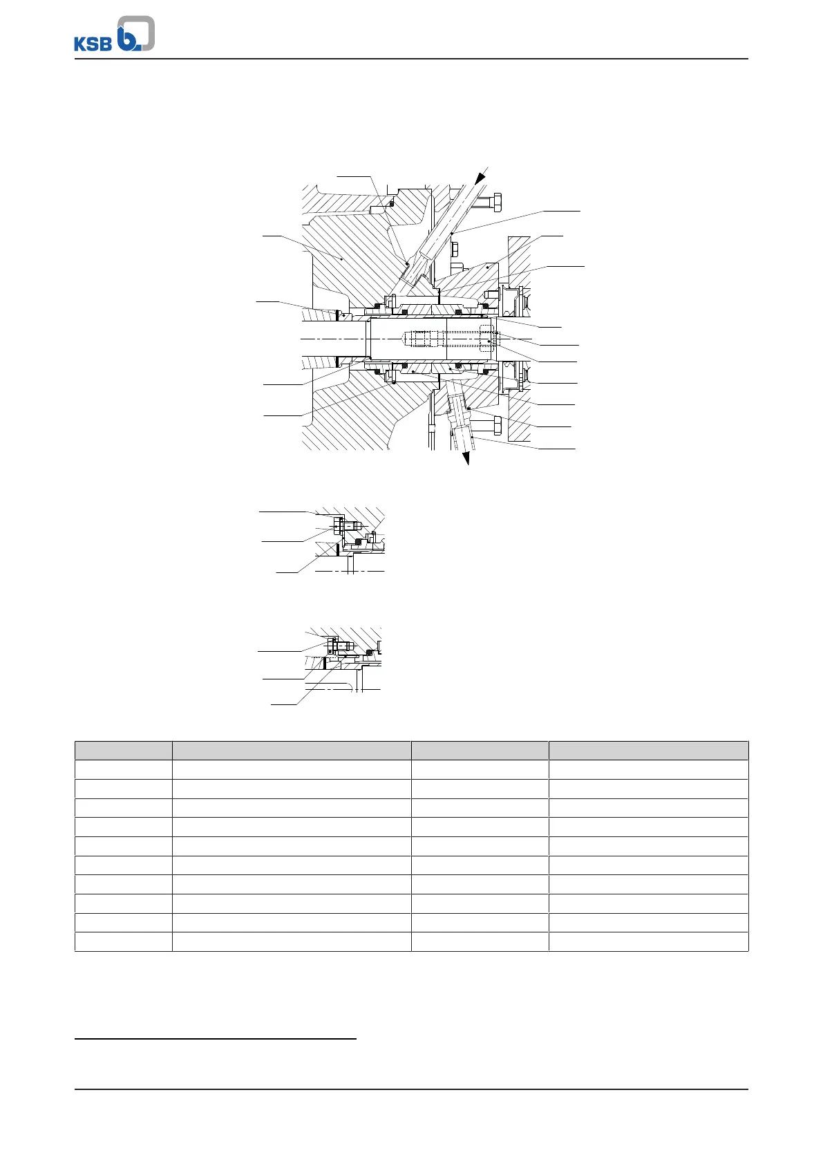
1.6.1 Shaft units 25/35
411.13
720.13
471
400.15
523
902.02
920.02
433.02
433.01
411.14
720.14
10A
10E
161
525
400.75
932.05
UG1385256_D01_001
Fig.3: Variant with double mechanical seal in back-to-back arrangement
550.24
901.24
575
UG1385256_D01_004
Fig.4: Position of anti-rotation device SU25
550.24
901.24
575
UG1385256_D01_005
Fig.5: Position of anti-rotation device SU35
Part number Description Part number Description
161 Casing cover 720.13/.14 Fitting
400.15
5)
/.75 Gasket 901.24 Hexagon head bolt
411.13/.14 Joint ring 902.02 Stud
433.01 Mechanical seal (inboard) 920.02 Nut
433.02 Mechanical seal (outboard) 932.05 Circlip
471 Seal cover
523 Shaft sleeve Auxiliary connections
525
6)
Spacer sleeve 10A Barrier fluid outlet
550.24 Disc 10E Barrier fluid inlet
575 Strip
5) Only for shaft unit25: joint ring 411.15
6) For shaft unit35 only; shaft unit see data sheet.