SERVICE WORK ON THE CHASSIS 11
61
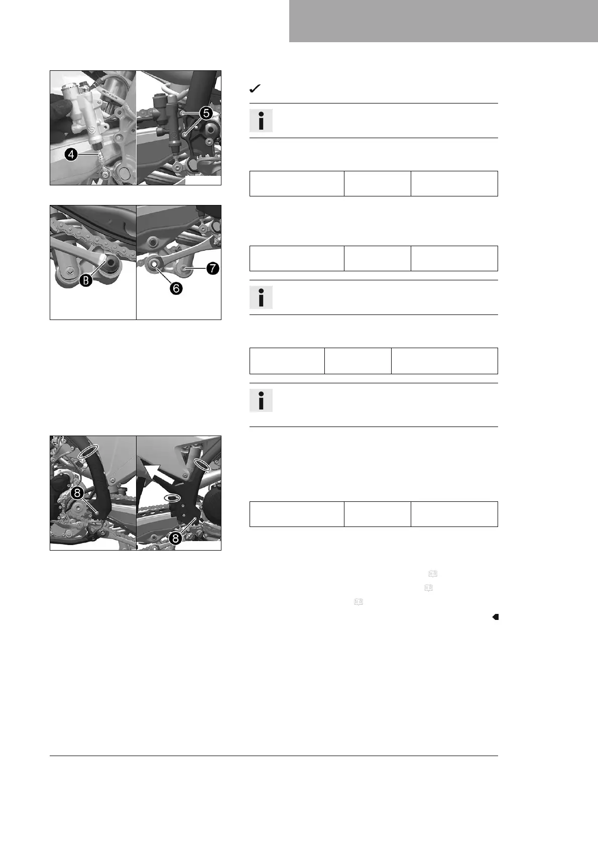
S05356-10
– Position the foot brake cylinder.
Push rod
4
engages in the foot brake cylinder.
Info
Ensure that the dust boot is correctly seated.
–
Mount and tighten screws
5
.
Guideline
Remaining screws,
chassis
M6 10 Nm (7.4 lbf ft)
S05348-10
– Position the angle lever and linkage lever.
–
Mount and tighten fitting
6
.
Guideline
Nut, linkage lever on
angle lever
M16x1.5 60 Nm (44.3 lbf ft)
Info
Pay attention to flat area
B
.
–
Mount and tighten screw
7
.
Guideline
Screw, bottom
shock absorber
M10 60 Nm (44.3 lbf ft)
Loctite
®
2701™
Info
Raise the link fork slightly to be able to mount the
screw more easily.
S05349-10
– Position the left frame protector.
– Insert the right frame protector from below and push it to the
rear.
–
Mount and tighten screws
8
with the washers.
Guideline
Screw, frame protec-
tor
M5 3 Nm (2.2 lbf ft)
– Mount the new cable ties.
Finishing work
– Check the free travel of the foot brake lever. ( p. 87)
– Remove the motorcycle from the lift stand. ( p. 49)
– Install the main silencer. ( p. 67)
 Loading...