TRANSMISSION
B2301, B2601, WSM
2-M22
[5] INDEPENDENT PTO
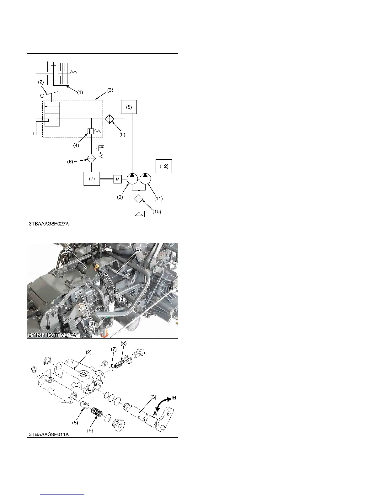
(1) Hydraulic Circuit
9Y1211156TRM0019US0
(2) Independent PTO Control Valve
Independent PTO control valve (2) is located at
transmission case (1).
The independent PTO control valve (2) consists of
PTO arm (3), poppet (5), ball (7) and etc..
The PTO arm (3) is connected to control rod (4) and
the independent PTO lever.
The PTO arm (3) is moved to "OFF" or "ON"
position by the independent PTO lever.
Oil passage in the PTO arm (3) is turned by the
independent PTO lever.
When the PTO arm (3) is moved to "OFF" position,
oil in the independent PTO control valve does not flow to
the oil passage.
When the PTO arm (3) is moved to "ON" position, oil
in the independent PTO control valve flow to the oil
passage.
Poppet (5) and spring (6) operate as a relief valve.
9Y1211156TRM0020US0
(1) PTO Clutch
(2) Independent PTO Lever
(3) Independent PTO Control
Valve
(4) Relief Valve
(5) Oil Cooler
(6) Oil Filter Cartridge (for HST)
(7) HST
(8) Power Steering
(9) Hydraulic Pump
(for HST, Power Steering
and Independent PTO)
(10) Oil Filter Cartridge
(11) Hydraulic Pump
(3-Points Hitch)
(12) 3-Points Hitch
(1) Transmission Case
(2) Independent PTO Control
Valve
(3) PTO Arm
(4) Control Rod
(5) Poppet
(6) Spring
(7) Ball
(8) Spring
A: PTO arm "OFF" position
B: PTO arm "ON" position

 Loading...


