ELECTRICAL SYSTEM
B2301, B2601, WSM
8-M4
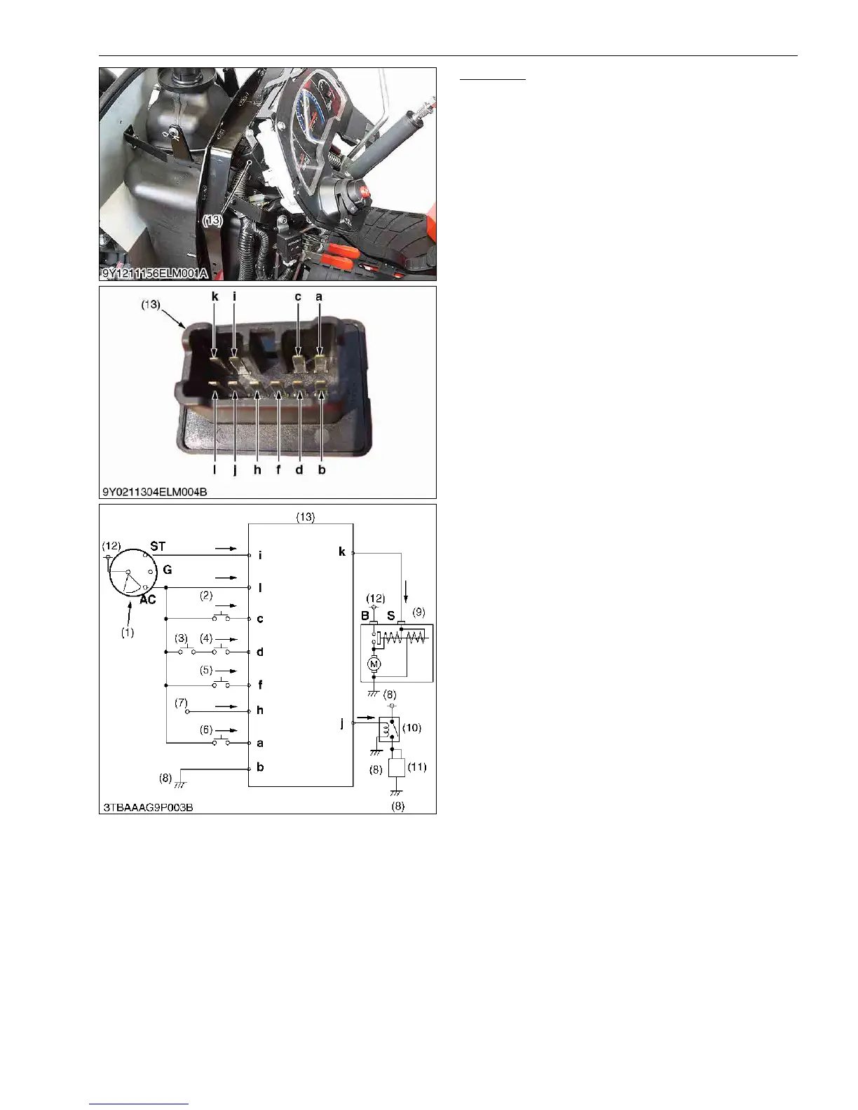
Controller
Controller is located inside the panel board.
Current from the key switch, safety switches and
regulator flows to controller.
Controller receives current as data, processes the
data, and sends out current computing results to starter
motor, relay (engine stop solenoid), and engine stop
solenoid.
OPC controller (13) controls engine starting and
engine stopping.
Current flows from battery to controller.
Current from switches such as PTO clutch lever
switch (2), PTO select lever switch (3), seat tilt switch (4),
seat switch (5), HST pedal switch (6), flows to the
controller.
Current from regulator (7) flows to the controller.
When starting the engine, the controller (13) supplies
current to starter motor S terminal and relay (engine stop
solenoid) (10).
Controller (13) receives data, processes the data,
and sends out the computing results.
Controller (13) receives data from safety switches,
processes the data inside the controller itself, and sends
out the computing results to starter motor (9) for engine
starting, and relay (engine stop solenoid) (10) for engine
stopping.
9Y1211156ELM0005US0
(1) Key Switch
(2) PTO Clutch Lever Switch
(3) PTO Select Lever Switch
(4) Seat Tilt Switch
(5) Seat Switch
(6) HST Pedal Switch
(7) Regulator
(8) Frame Earth
(9) Starter Motor
(10) Relay (Engine Stop
Solenoid)
(11) Engine Stop Solenoid
(12) Battery
(13) OPC Controller
a to l: Controller Terminal
ST: Key Switch ST Terminal
G: Key Switch G Terminal
AC: Key Switch AC Terminal
B: Starter Motor B Terminal
S: Starter Motor S Terminal
→: Current Flow

 Loading...


