ELECTRICAL SYSTEM
B2650HSDC, B3350HSDC, WSM
8-S29
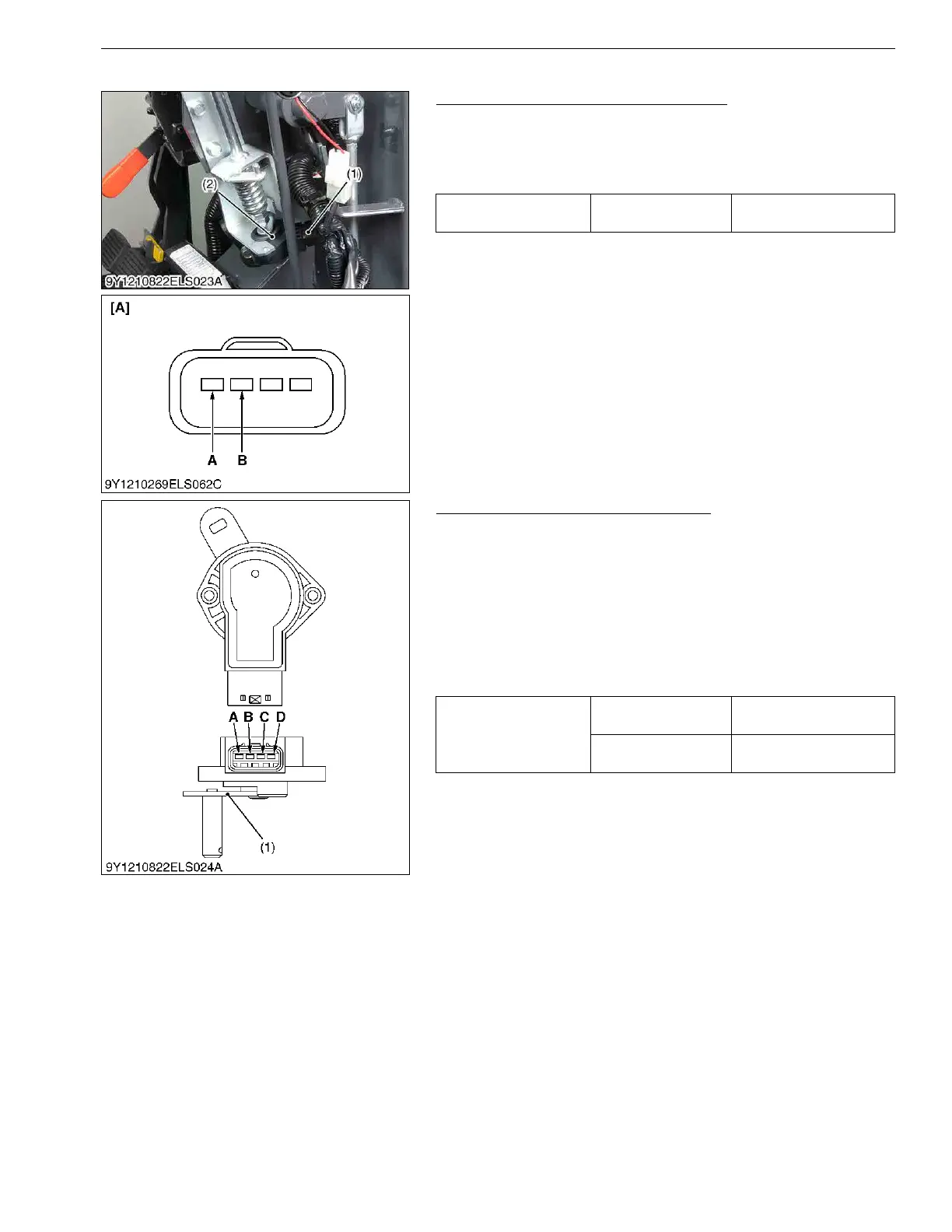
(5) Accelerator Lever Sensor
Accelerator Lever Sensor Input Voltage
1. Remove the accelerator lever sensor connector (1).
2. Turn the main key switch ON.
3. Check the voltage between terminal A (+) and terminal B (−) of
the wire harness side.
9Y1210822ELS0061US0
Accelerator Lever Sensor Resistance
1. Measure the resistance between terminal A and C while slowly
turning the sensor lever (1).
2. Then, check resistance between terminal B and C while slowly
turning the sensor lever (1).
3. It is OK if the resistance value is approximate to the value shown
in the table below.
(Reference)
• The change of resistance can be checking easily when an
analog tester is employed.
9Y1210822ELS0062US0
Voltage
Terminal A –
Terminal B
5 V
(1) Accelerator Lever Sensor
Connector
(2) Accelerator Lever Sensor
[A] Connector (Harness)
A : Terminal A
B : Terminal B
Resistance
Terminal A –
Terminal C
0 to 1 kΩ
Terminal B –
Terminal C
0 to 1 kΩ
(1) Sensor Lever A : Terminal A
B : Terminal B
C : Terminal C
D : Terminal D