9-S62
L3540, L4240, L5040, L5240, L5740, WSM
ELECTRICAL SYSTEM
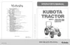
Brake Lamp Switch Continuity
1. Disconnect the connector, and measure the resistance with an
ohmmeter between connector terminal.
2. If the measurement differs from the table below, the brake switch
is faulty.
W1024163
[9] WARNING LAMPS
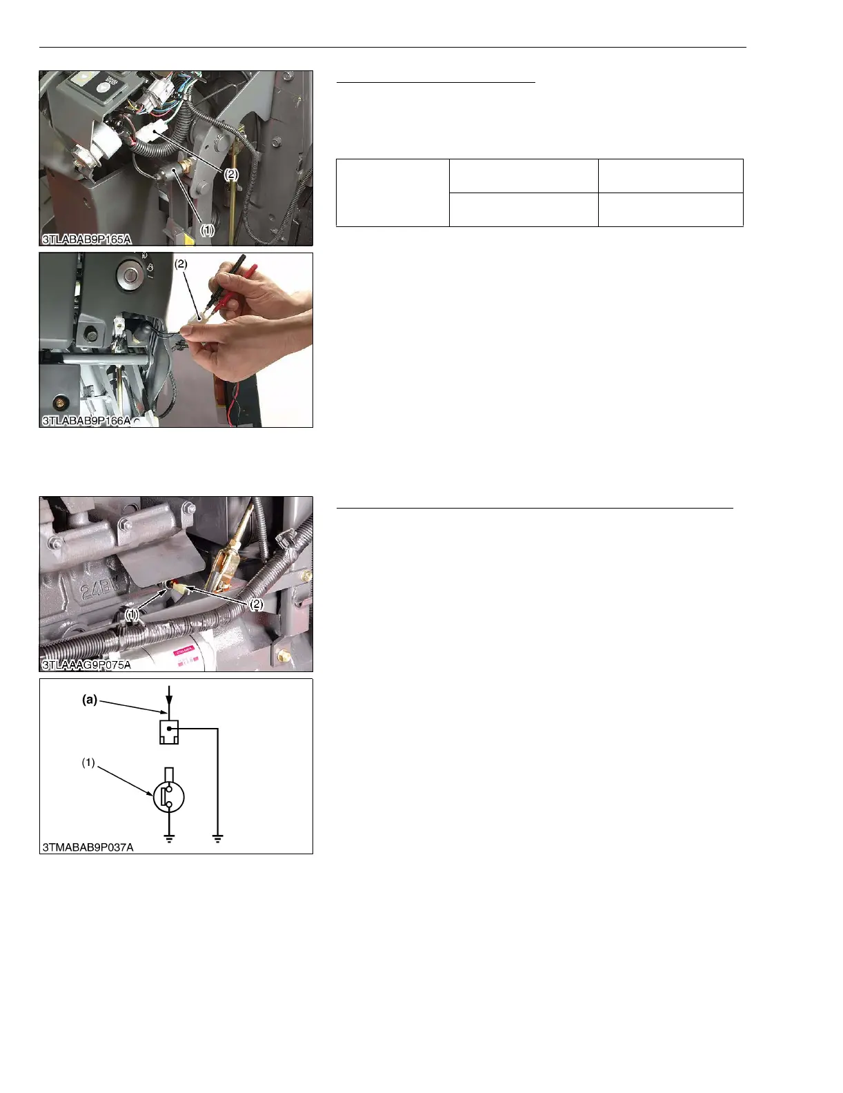
(1) Checking
Engine Oil Pressure Switch Panel Board and Wiring Harness
1. Disconnect the lead (2) from the engine oil pressure switch after
turning the main switch OFF.
2. Turn the main switch ON and connect a jumper lead from the
lead to the chassis.
3. If the engine oil pressure indicator lamp does not light, the panel
circuit or the wiring harness is faulty.
W10259540
Resistance
between connector
terminals
When brake pedal is
released
Infinity
When brake pedal is
depressed
0 Ω
(1) Brake Lamp Switch (2) Brake Lamp Switch Connector
(1) Engine Oil Pressure Switch
(2) Switch Lead
(a) From Oil Pressure Lamp

 Loading...