FRONT LOADER
LA525, LA765, WSM
1-S17
5. CHECKING, DISASSEMBLING AND SERVICING
[1] CHECKING AND ADJUSTING
(1) Relief Valve
Relief Valve Setting Pressure
• When removing the plug from hydraulic cylinder, be sure to
lower the three point hitch.
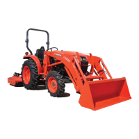
1. Remove the plug from hydraulic cylinder.
2. Connect the cable and pressure gauge to hydraulic cylinder
(thread size : G1/4).
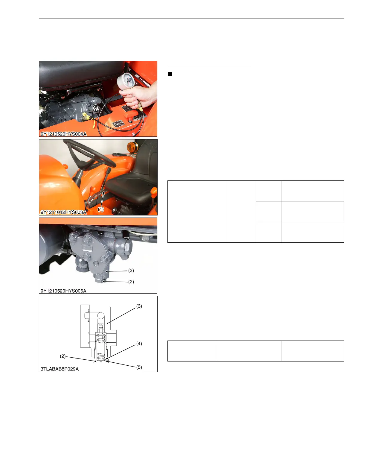
3. Remove the position control lever stopper (1).
4. Start the engine and set at maximum speed.
5. Move the position control lever all way up to operate the relief
valve and read the gauge.
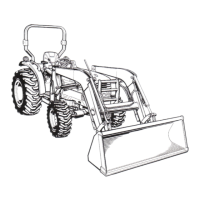
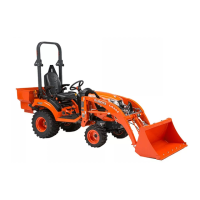
6. If the pressure is not within the factory specifications, remove
the relief plug (2) of front hydraulic block (3) and adjust with the
adjusting shims (4).
7. After the relief valve setting pressure test, reset the position
control lever stopper firmly.
Condition
• Engine speed:
Maximum
• Oil temperature:
40 to 60 °C (104 to 140 °F)
(Reference)
• Thickness of shims (4):
0.1 mm (0.004 in.)
0.2 mm (0.008 in.)
0.4 mm (0.02 in.)
• Pressure change per 0.1 mm (0.004 in.) shim:
Approx. 260 kPa (2.7 kgf/cm
2
, 38 psi)
• When shims are added, the pressure increases.
9Y1211014FLS0009US0
Relief Valve Setting
Pressure
Factory
specifica-
tion
L2501
15.2 to 16.2 MPa
155 to 165 kgf/cm
2
2210 to 2340 psi
L3301/
L3901
15.7 to 16.6 MPa
160 to 170 kgf/cm
2
2280 to 2410 psi
L4701
17.1 to 18.1 MPa
174 to 185 kgf/cm
2
2480 to 2630 psi
Tightening torque Relief plug
49 to 68 N·m
5.0 to 7.0 kgf·m
37 to 50 lbf·ft
(1) Stopper
(2) Relief Plug
(3) Front Hydraulic Block
(4) Adjusting Shim
(5) Washer