3-S25
B1710 · B2110 · B2410 · B2710, WSM
TRANSMISSION
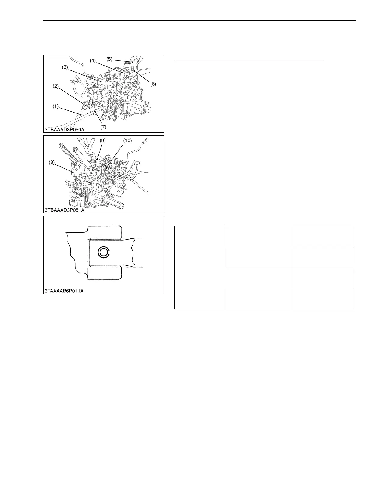
[4] DISASSEMBLING TRANSMISSION CASE
(1) Manual Transmission Model
Separating Hydraulic Cylinder and Main Shift Cover
1. Remove the connecting pipe (7).
2. Tap out the spring pins and remove the universal joint (2) with
front wheel drive propeller shaft (1).
3. Remove the external snap ring and remove the rear PTO shift
lever (6) with rod, range gear shift lever (5) and mid-PTO shift
lever (4).
4. Remove the top link bracket LH (8).
5. Remove the connecting plate (10) and hydraulic cylinder
mounting screws and remove the hydraulic cylinder assembly
(9).
6. Remove the main shift cover mounting screws and remove the
main shift cover (3) with differential lock pedal.
(When reassembling)
• When inserting the spring pins, face their splits in the direction
parallel to the universal joint as shown in the figure.
• Apply liquid gasket (Three Bond 1208D or equivalent) to joint
face of the main shift cover to transmission case and differential
case to the hydraulic cylinder.
• Apply grease to the spline of the front wheel drive propeller shaft,
universal joint and ball coupling.
• Reinstall the connecting pipe with O-rings and back-up ring
securely.
W10193920
Tightening torque
Connecting plate mounting
screw and nut
39.2 to 44.1 N·m
4.0 to 4.5 kgf·m
28.9 to 32.5 ft-lbs
Top link bracket mounting
screw
77.5 to 90.1 N·m
7.9 to 9.2 kgf·m
57.2 to 66.5 ft-lbs
Hydraulic cylinder
mounting screw
39.2 to 44.1 N·m
4.0 to 4.5 kgf·m
28.9 to 32.5 ft-lbs
Main shift cover mounting
screw
17.7 to 20.6 N·m
1.8 to 2.1 kgf·m
13.0 to 15.2 ft-lbs
(1) Front Wheel Drive Propeller Shaft
(2) Universal Joint
(3) Main Gear Shift Cover
(4) Mid-PTO Shift Lever
(5) Range Gear Shift Lever
(6) Rear PTO Shift Lever
(7) Connecting Pipe
(8) Top Link Bracket LH
(9) Hydraulic Cylinder Assembly
(10) Connecting Plate
 Loading...

