8-M5
B1710 · B2110 · B2410 · B2710, WSM
HYDRAULIC SYSTEM
4. POSITION CONTROL VALVE
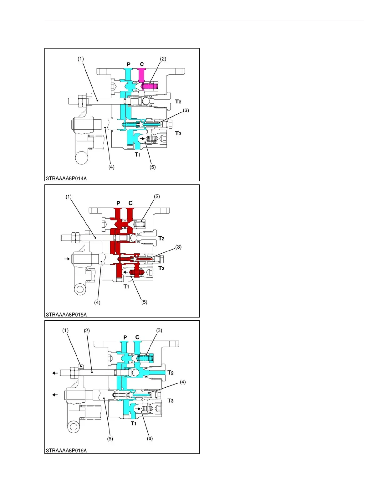
■ Neutral
Oil forced into the control valve through the P port
pushes open the unload poppet (5) and then returns to
the transmission case through the T
1 port.
Oil behind the unload poppet (5) returns to the
transmission case through the spool (4) and the T
3 port.
Since the poppet 2 (1) and poppet 1 (2) are closed, oil
in the hydraulic cylinder does not flow to the transmission
case. Thus, the implement remains at its fixed position.
W10136350
■ Lift
When the control lever is set to the LIFT position, the
spool (4) is move to the right.
The oil forced into the control valve through the P port
flows to the back of the unload poppet (5) to close it.
The oil pushes open the poppet 1 (2), and flows into
the hydraulic cylinder through the C port to lift the
implement.
W10137360
■ Down
When the control lever is moved to DOWN position,
the spool (5) is move to the left, and the poppet 2 (2) is
also move to the left by the lever (1).
Oil in the hydraulic cylinder is forced out to the
transmission case through the T
2 port by the weight of
the implement, causing the implement to lower.
Oil forced into the control valve through the P port
pushes open the unload poppet (6) and returns to the
transmission case through the T
1 port.
W10138410
(1) Poppet 2
(2) Poppet 1
(3) Plunger
(4) Spool
(5) Unload Poppet
P : Pump Port
C : Cylinder Port
T
1, T2, T3 : Tank Port
(1) Poppet 2
(2) Poppet 1
(3) Plunger
(4) Spool
(5) Unload Poppet
P : Pump Port
C : Cylinder Port
T
1, T2, T3 : Tank Port
(1) Lever
(2) Poppet 2
(3) Poppet 1
(4) Plunger
(5) Spool
(6) Unload Poppet
P : Pump Port
C : Cylinder Port
T
1, T2, T3 : Tank Port
 Loading...

