6| Function description
Overview of the machine parts
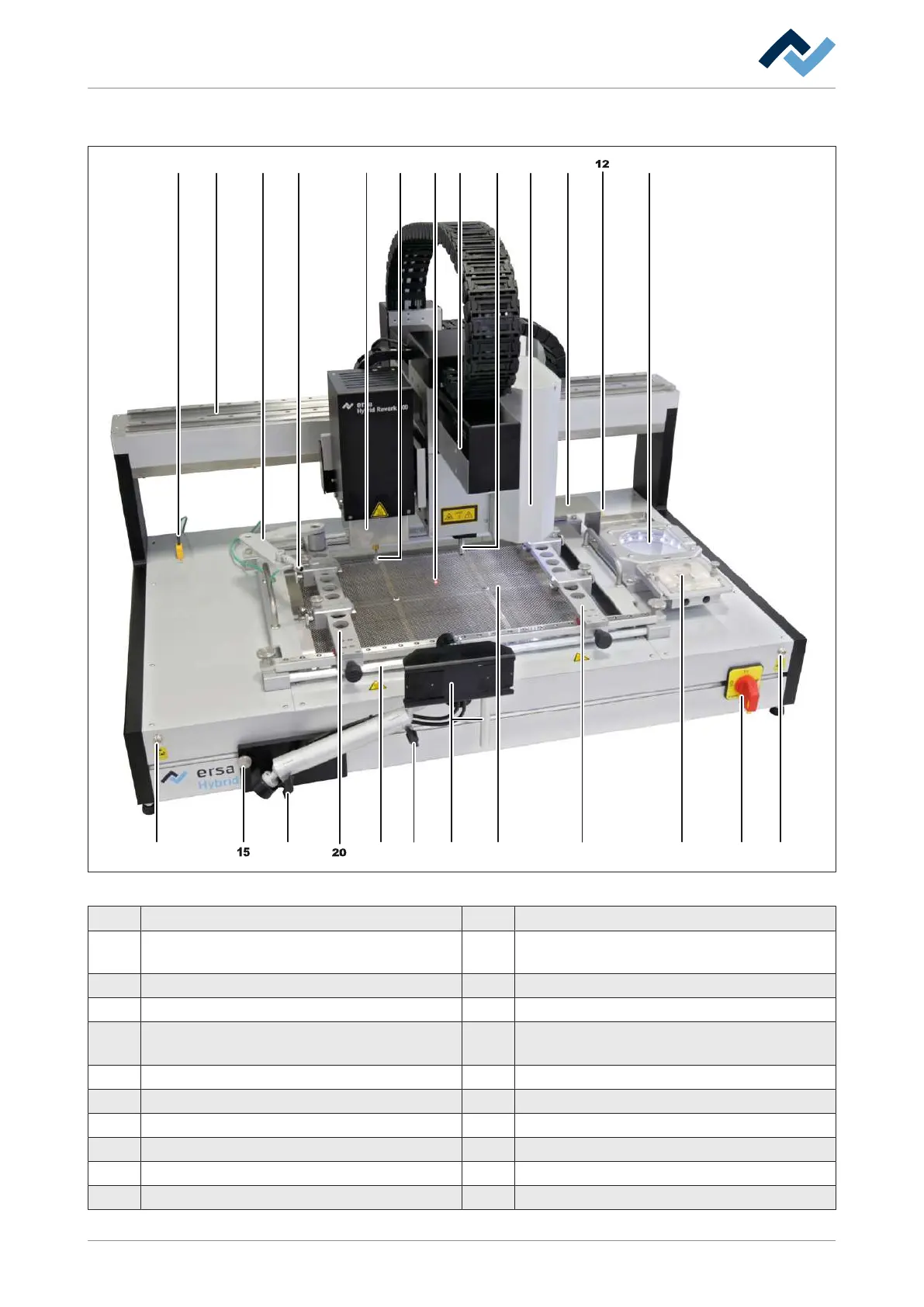
6.2 Overview of the machine parts
7 1310 118
16 1614 1418 222017 19
21
52 3 41 96
Fig.11: Overview of the machine parts
1 Connection socket thermocouple 1 (TE1) 12 Connection socket thermocouple 2 (TE2)
2 X axle 13 Glass plate, component support and component
identification
3 Telescopic holder for the thermocouple 14 Connection for the ESD strap
4 Thermocouple 1 15 Fastening screw for the optional RPC camera
5 Heating head, height-adjustable 16 Location screw position for the optional RPC
camera
6 Pipette 17 Air baffle pipe cooling
7 Laser beam for component positioning 18 Optional RPC camera
8 Y axle 19 Lower heating, 3 zones
9 Pick-and-place nozzle 20 Insertion frame
10 Upper camera 21 Dip & Printstation holder
11 Storage tray for desoldered components 22 Main switch, lockable
Ersa GmbH 3BA00207_01 Operating Instructions HR 600_2|Rev. 3 52/169
 Loading...