6| Function description
The user interface
6.4.4 The parameter windows
Start Camera and light Placement View Extras
Connect
Data accessesControl Record processes Analysis functions
Delete Archiving
Recording
Diagram
settings
Soldering
Placement
Profile library
Archive
Save target position
System info
Power monitor:
Soldering
No error
Standby
Actual parameters
Data table
System settings System info
System parameters
Unit-ID:
Serial number:
Firmware
Expert data
Internal temperature:
Operating hours:
T. heater hours:
Laser:
Fan:
Vacuum Pip.
Vacuum PL.
Cooling bottom:
Head motor:
End switch top:
End switch bottom:
Pipette motor:
End switch pipette:
Top heater:
Bottom heater:
up:
up:
down:
down:
X-Axis Y-Axis Z-Axis
Angle of rotation
1
6
4
5
3
7
2
Open
Save Print
CSV
Export
Cursor
Add
dot
Delete
dot
Delete
all dots
8
Change
user
Setpoint
curve
Online-HR 600
Current image
Archive
Profiles
Style
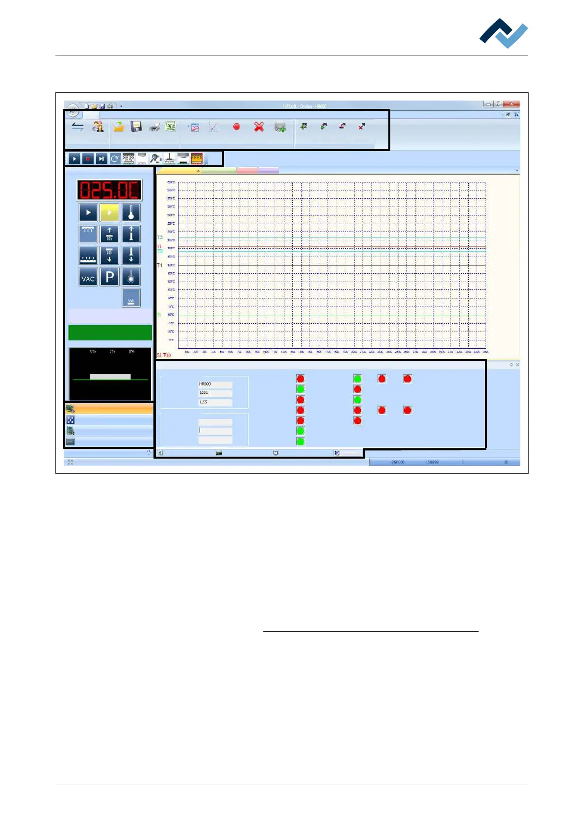
Fig.21: The parameter window (7)
Parameter windows are displayed in portion (7)
In the lower section of the parameter window are the tabs for:
– [Actual parameters]
– [Data table]
– [System settings]
– [System info]
Depending on the tabs activated, the parameter window changes its appearance.
You can determine which tabs ought to be displayed. With regard to this, please
read the chapter Customizing the presentation of charts and windows [}87].
Ersa GmbH 3BA00207_01 Operating Instructions HR 600_2|Rev. 3 79/169
 Loading...