68221
actual
size
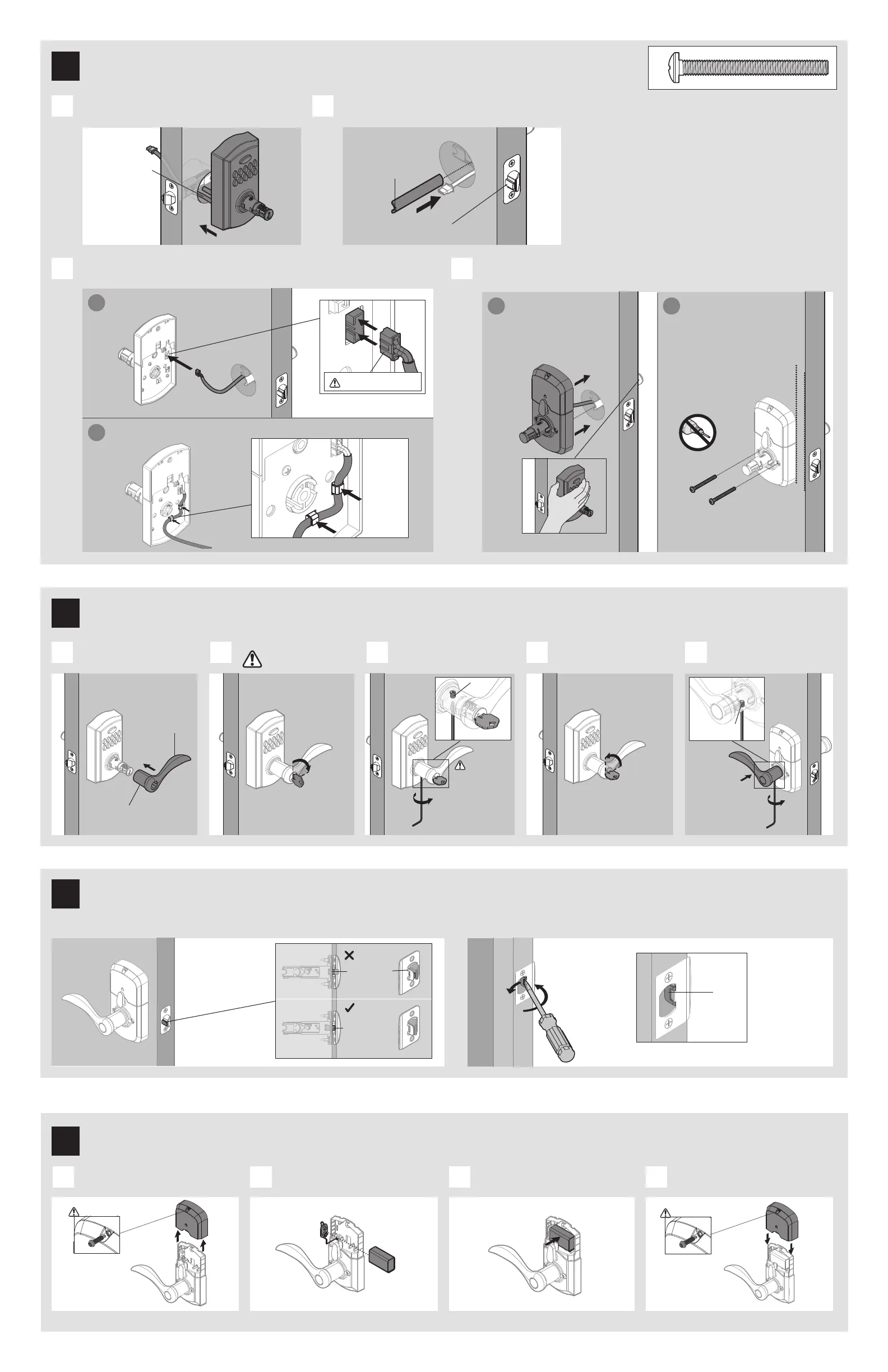
Connect and secure cable to interior assembly.
C
a
b
Connect cable.
Ensure tight cable connection.
Insert key and
turn 90° clockwise.
Tighten pre-installed set screw
to secure exterior lever.
Turn key back to vertical
position to remove it.
Install and secure
interior lever.
Install exterior lever.
A B C D E
Tighten
pre-installed
set screw.
If latch is loose in the
strike, adjust the strike
tab so it grips the latch
bolt better when the
door is closed.
tab
Close door, test latch operation and make adjustments as needed:
small bolt in
strike hole
small bolt NOT
in strike hole
Lever handle
faces away
from the latch.
J1 or
J2
K
Route cable through clips.
a
Install interior assembly
while holding the exterior
assembly. Make sure the
spindle fully engages with
the interior assembly.
b
Secure interior assembly
with mounting screws.
K
Q (2x)
Connect 9V battery. Secure battery into interior
assembly.
Reinstall battery cover.Remove interior cover.
A B C D
L
Hold exterior assembly.
M
Red side must face left.
The small bolt of the
latch should not enter
the strike hole. If it
enters the strike hole,
reposition strike.
Hole on lever
faces down.
To access
the hidden
pre-installed set
screw on the
lock, the key
must be turned
horizontal.
set
screw
H
H
set
screw
H
J1 or
J2
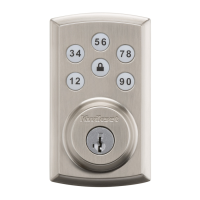
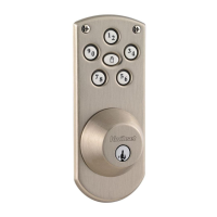
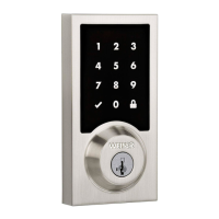
Install exterior keypad.
rounded edge
faces latch
latch
Install spindle.
Install interior assembly and secure with mounting screws.
A B
D
cable goes
under latch
Q
Ensure both interior and
era seilbmessa roiretxe
parallel to edge of door
before securing.
Note:
Tighten screws evenly
and do not overtighten .
2 / 4
3
4
Install the exterior keypad, spindle, and interior assembly
5
6
Install levers
Test latch operation
Install battery
G
F
H
To remove the
interior cover,
you must remove
the security screw
on the cover.
Replace the
security screw
on the cover.