2T6/2T7/2T8/2T9-3
1-5-22
1-5-10 PWBs
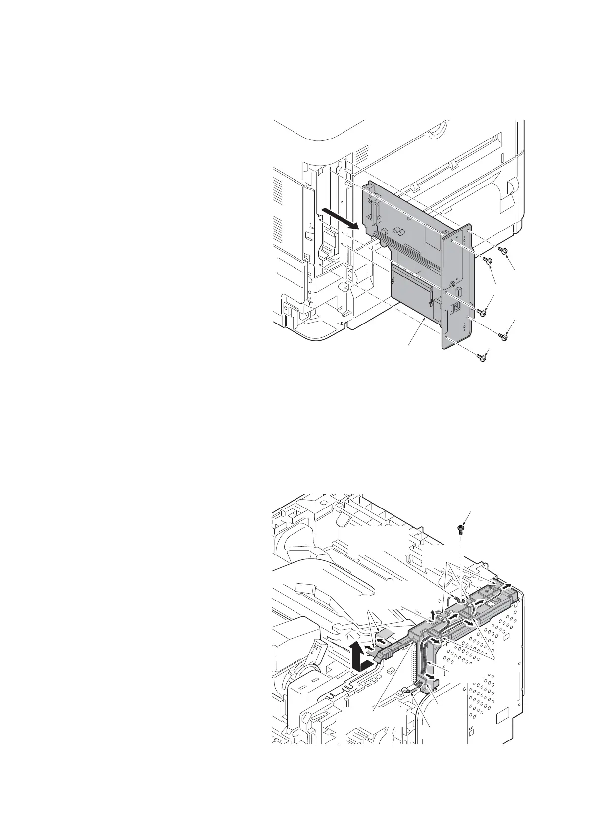
(1) Detaching and refitting the main PWB
Procedure
1. Remove the inlet cover and the slot
cover.(See page 1-5-3)
2. Unplug the power cable.
Caution: Do not insert or remove main
PWB assembly while machine power is
on.
Doing so may cause damage to the
machine and the main PWB.
3. Remove five screws and then pull the
main PWB assembly out forward.
4. Check or replace the main PWB and
refit all the removed parts.
Figure 1-5-33
*: Re-activate the license if optional licensed product is installed.
1) Card Authentication Kit(B)
2) UG-33 (ThinPrint)
3) Data Security Kit(E)
Re-input four-digit encrypted code that was input at setup.
*: Reset the user initial values from the System Menu and Command Center.
(2) Detaching and refitting the engine PWB
Procedure
1. Remove the top cover assembly.
(See page 1-5-3)
2. Remove the right upper cover.
(See page 1-5-4)
3. Remove the main PWB assembly.
(See page 1-5-22)
4. Remove the screw and then the
grounding terminal.
5. Remove two FFCs from inside of frame.
6. Release the wires and FFC from hooks.
7. Release the fixing hook and then
remove the wire guide.
Figure 1-5-34
Screw
Screw
Screw
Screw
Main PWB assembly
Wire guide
The hook
for fixation
Hook
FFC
Hooks
Hooks
Wires
Screw
Grounding
terminal
FFCs
 Loading...