MTC Failure Display Specification for K5BMC EI
Document No. Z914-C73000030E Ver. 5
12. Feb. 2011 P 1 / 25
1. Scope
This document applys to display indication of Maintenance Console(MTC).
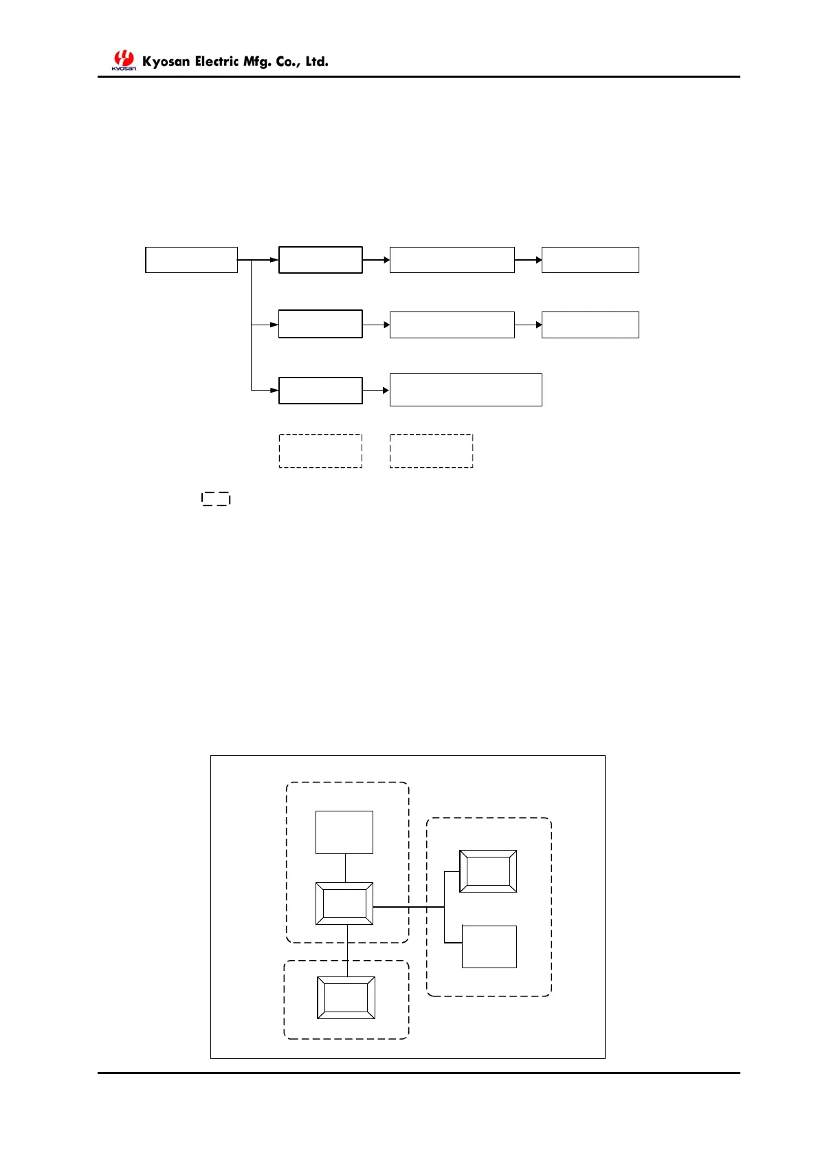
2. Display Transition Diagram
3. MTC DISPLAY
3.1 General System Display
General System Display is shown on the MTC.
Unless specified, system status is to be indicated in green for normal and in red for abnormal.
In case of abnormality, the audio alarm is provided.
Switching from the General System Display below to linked display, e.g. LOGIC RACK,
OUTFIELD EQUIPMENT or CONTROL PANEL, can be achieved by pressing each button.
General System
DISPLAY
LOGIC
RACK
CONTROL PANEL
POINT MOVEMENT and
FILAMENT BURN OUT
CONTROL
PANEL
Operator
Console
(OPC)
OUTFIELD
EQUIPMENT
LOGIC Rack
(Logic Rack Mounting Display)
(Block Button)
Dot-line shows only status indication and not Button.
Each Card
Each Card
(Card Level Display)
(Control Panel Display)
(Block Button)
(Card Level Display)
(Out Field Equipment Display)
Maintenance
Console
(MTC)
(Block Button)
OUTFIELD
EQUIPMENT
LOGIC
RACK
OPERATOR ROOM
CONTROL
PANEL
OPC
FIELD
RELAY ROOM
MTC


 To Next Page