7
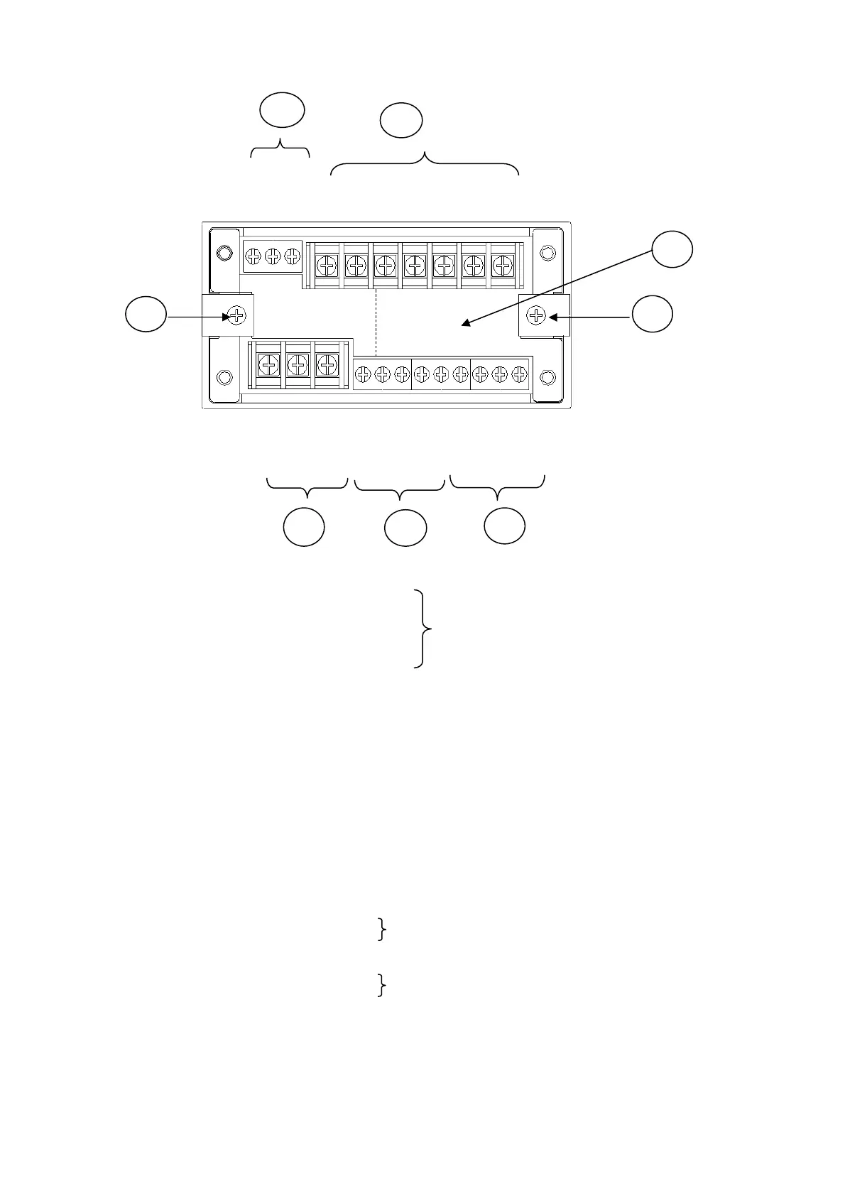
1-2 REAR PANEL
1) Optional Function: Location of connectors of BCD, RS232C, and RS485
2) Connection Terminals of Transducers (Transducer and TEDS)
A : Bridge excitation (+) Red wire
B : Bridge output (-) White wire
C : Bridge excitation (-) Black wire
D : Bridge output (+) Green wire
E : Shield
+ : TEDS (+)
- : TEDS (-)
3) Analog Output Terminal (ANALOG OUT)
COM : Common
V : Voltage output terminal
I: Current output terminal
4) Control Output Terminal (OUTPUT) 5) Control Input Terminal (INPUT)
COM: Common COM: Common
1 : High limit output (HIGH) 1 : Digital Zero command
2 : OK output (OK) 2 : Level test command
3 : Low limit output (LOW) 3 : Pattern select command 1
4 : Pattern select command 2
6) Power Input Terminal (POWER)
GND: Ground terminal .
N : Power supply input terminal
L : Power supply input terminal
+ : +Power supply input terminal
- : -Power supply input terminal
7) Fitting Metal Used for fixing the WGI-400A to the panel.
1)
2
3
4)
V I
A B C D E + -
N L 1 2 3
G
N
D
C
O
M
C
O
M
C
O
M
1 2 3 4
6)
(+ -)
5)
7
7)
KYOWA’s standard wire colors
Connect AC power supply.
Connect DC power supply. (When DC is optionally set.)