5
1. PARTS NAMES AND FUNCTIONS
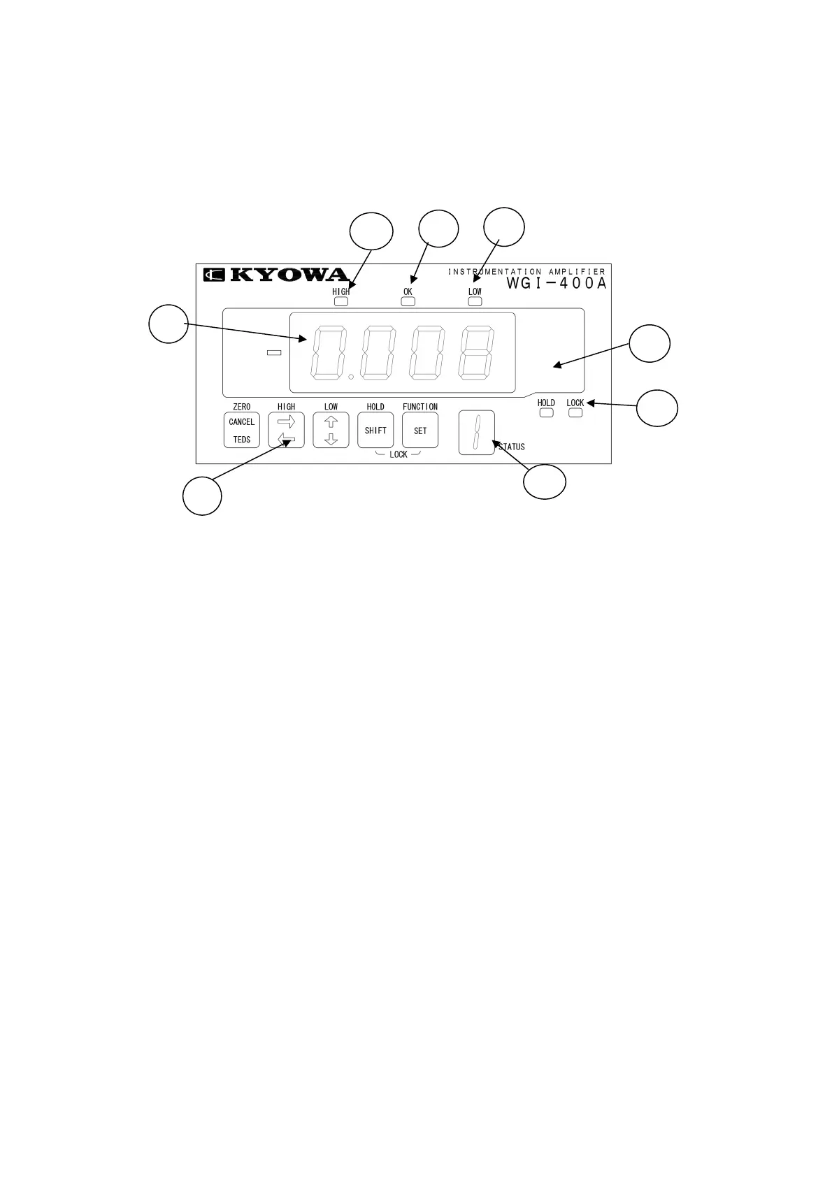
1-1 FRONT PANEL
1) Indicator .................................... • Displays measured value, various selected functions, and set values.
• Normally, it is displayed with measured value according to the output
from transducers. However, if error occurs, error message appears.
2) Unit Label .................................. • Select the desired unit from the accessory unit label sheet and attach it
on this portion.
3) [LOCK] LED ............................. • When this [LOCK] LED is lit or flickering, no functions are set. Always
turn OFF the [LOCK] LED before setting functions.
• However, high/low limit value is displayed even when the [LOCK] LED
lit.
4) [HIGH] Limit LED .................... • Lights up when the measured value exceeds the high limit value.
• Flickers when the high limit value is displayed.
5) [OK] LED .................................. • Flickers when the measured value exceeds the low limit value or lowers
the high limit value.
6) [LOW] Limit LED ..................... • Lights up when the measured value is less than the low limit value.
Flickers when the low limit value is displayed.
7) Operation Key ............................. • A pushbutton switch to operate the WGI-400A.
One key is used together for multiple functions that are automatically
switched according to measuring or setting states.
8) Status Indicator ............................ • In the measuring state, pattern No. is displayed.
• During calibration, minimum-digit numeric value of rated capacity is
displayed.
1)
2)
3
4)
5)
6)
7)
8