L-ACOUSTICS ARCS Manual V2.0 2/13/2003 3
LIST OF FIGURES
Figure 1: Conventional horn array versus an array of ARCS DOSC waveguides.....................................6
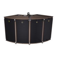
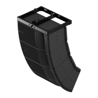
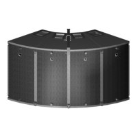
Figure 2: Array of 4 ARCS Enclosures ......................................................................................................6
Figure 3: ARCS System Block Diagram ....................................................................................................8
Figure 4: ARCS System Parts and Accessories .........................................................................................9
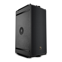
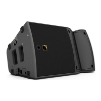
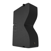
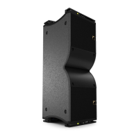
Figure 5: ARCS Enclosure.......................................................................................................................10
Figure 6: ARCPLA...................................................................................................................................11
Figure 7: ARCSCOV ...............................................................................................................................11
Figure 8: ARCOUPL ...............................................................................................................................12
Figure 9: BUMP3, LIFTBAR Rigging Accessories....................................................................................12
Figure 10: Examples of BUMP3 Requirements for 4 and 5 Element ARCS Arrays................................13
Figure 11: ARCBUMP.............................................................................................................................13
Figure 12: ARCSTRAP ............................................................................................................................14
Figure 13: ARCSTRAP, BUMP3, LIFTBAR Requirements for a 2 row x 4 element ARCS Array...........14
Figure 14: MLS switches on the rear panel of LA24a and LA48a amplifiers...........................................17
Figure 15: ARRAY Cutview simulation of an ARCS installation for theatrical sound reinforcement......29
Figure 16: AUTOCAD utilities for representing ARCS horizontal and vertical coverage......................30
Figure 17: ARCS Side-fill (3 x ARCS, 1 x SB218) plus stereo front-fill system. ......................................31
Figure 18: ARCS fill application (3 clusters of 4 x ARCS in an LCR configuration).................................31
Figure 19: ARRAY cutview simulation of an ARCS FOH system with delays.........................................33
Figure 20: L-ACOUSTICS Subwoofer Continuous Unweighted SPL Comparison................................34
Figure 21: Illustration of subwoofer time alignment...............................................................................36
Figure 22: Rigging procedure for a 4 enclosure ARCS array ..................................................................39
Figure 23: Rigging procedure for a 3 enclosure ARCS array ..................................................................40
Figure 24: Rigging procedure for a double row (4+4) enclosure ARCS array.......................................43
Figure 25: ARCBUMP rigging procedure for a 3 enclosure horizontal ARCS array...............................45
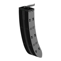
Figure 26: ARCS line drawing .................................................................................................................51
LIST OF TABLES
Table 1: Load and Power Ratings for ARCS ....................................................................................................15
Table 2a: Recommended Power Amplification and MLS switch settings for ARCS low section .................... 16
Table 2b: Recommended Power Amplification and MLS switch settings for ARCS high section ................... 16
Table 3: L-ACOUSTICS LA24a and LA48a Power Amplifier Specifications ...................................................17
Table 4: Maximum Recommended Length for Damping Factor > 20............................................................ 18
Table 5: XTA DP226 Presets .......................................................................................................................... 23
Table 6: XTA DP224 Presets .......................................................................................................................... 23
Table 7: BSS 366 Omnidrive Compact Plus Presets .......................................................................................24
Table 8: BSS 334 Minidrive Presets ................................................................................................................. 25
Table 9: BSS 336 Minidrive Presets ................................................................................................................. 26
Table 10: L-ACOUSTICS Subwoofer Specification Summary......................................................................... 34
Table 11: Subwoofer and Low Section Processing for ARCS 3-Way Presets ................................................. 35
Table 12: ARCBUMP Pick Point Hole Number versus Tilt Angle for 2, 3 or 4 ARCS.................................... 46
Table 13: ARCS Rigging Reference Chart........................................................................................................47