COMPONENT MAINTENANCE MANUAL
AVIATION RECORDERS
FA2100CVR
Page 307
Nov. 01/98
Disassembly
23–70–04
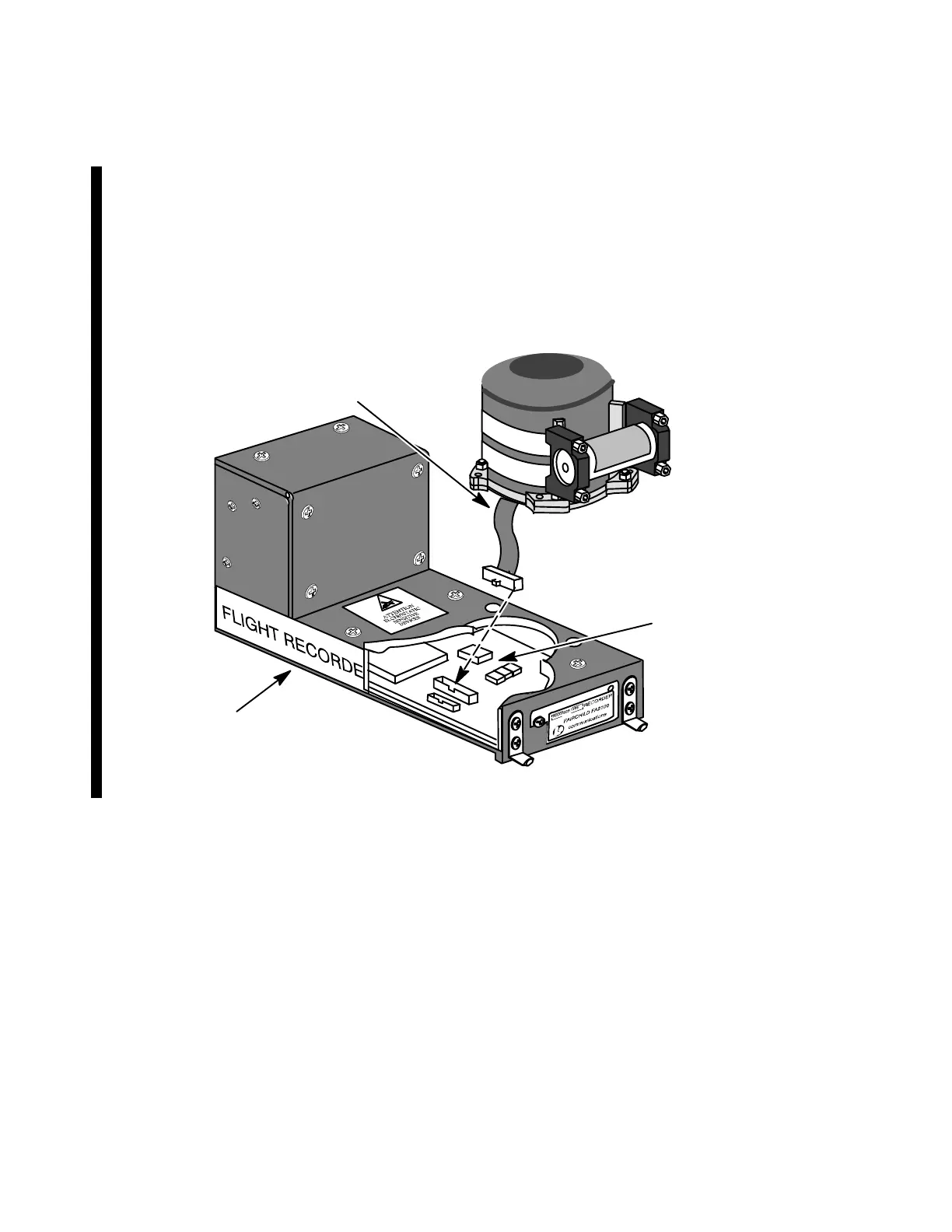
(c) For Post-MOD DOT 13 units only, carefully lift the CSMU memory assem-
bly directly up without pulling the memory interface cable to gain access to
the J5 connector located on the Acquisition Processor PWA (1-175).
Carefully unplug P1 of the Memory Interface Cable Assembly from J5 on
the Acquisition Processor PWA. Note the pins of J5 can be easily dam-
aged if handled incorrectly.
Memory Interface
Cable Assembly
P1
J1
Acquisition
Processor PWA
(AP)
CSMU
Memory Assembly
(1‐185)
(1‐175)
J5
Recorder
Chassis
(1‐5)
Figure 305. CSMU Memory Assembly Removal Diagram (POST-MOD DOT 13)
(4) For GACVR’s, p/ns: 2100−1010−5X and 2100−1020−5X, remove RTV from the
bottom of the CSMU and the Chassis at the seating surface for the CSMU memory
assembly.
(5) Lift the CSMU away from the chassis.
Dec. 09/1
Rev. 13 Page 307


 To Next Page