4
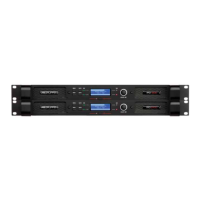
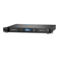
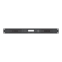
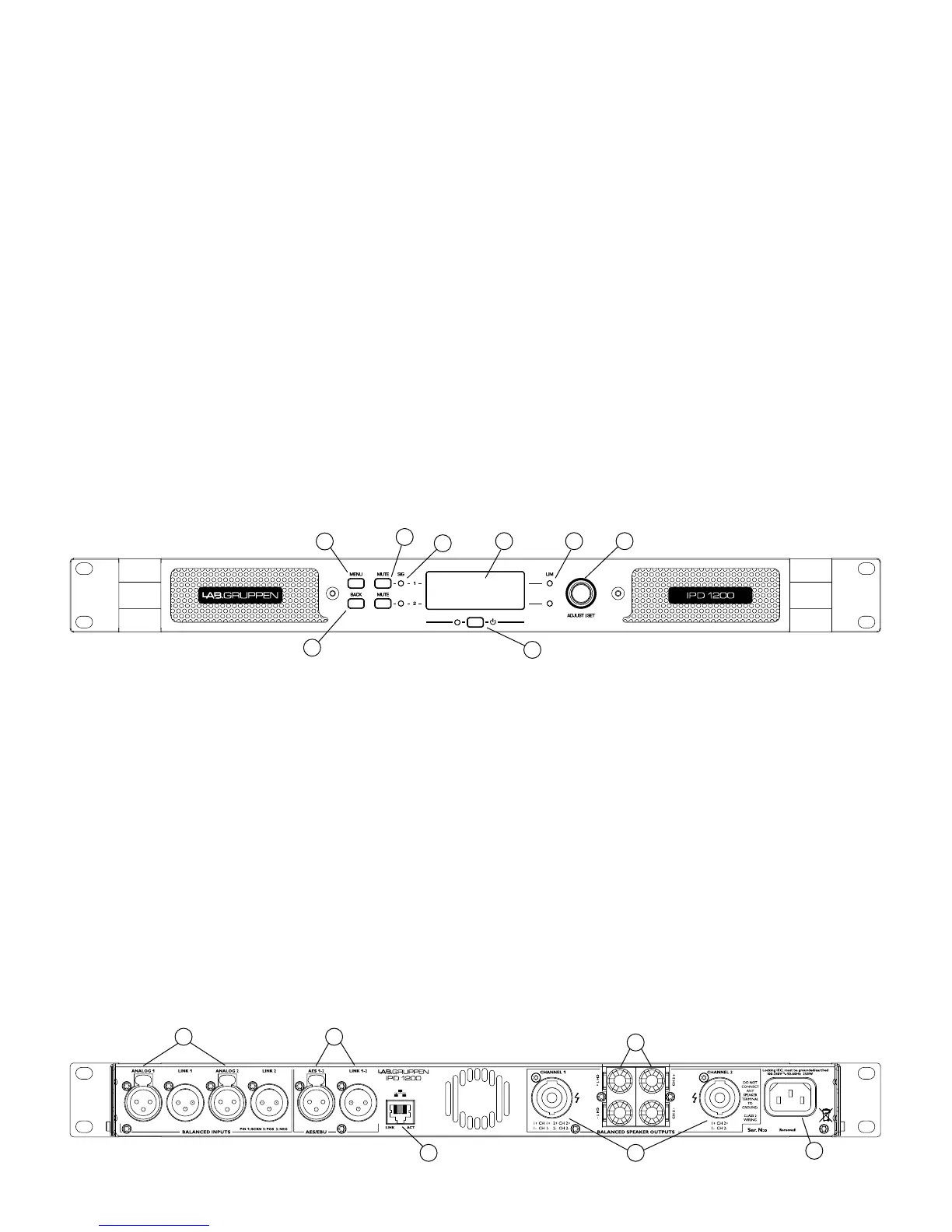
Front panel
The following indicators and controls are available on the front panel:
1 MENU – Selects MENU mode and conrms a given preset name.
2 BACK – Moves backward through menu layers in MENU mode.
3 MUTE – Mutes corresponding channel as indicated.
4 SIG – Illuminates green when signal is present. Illuminates red when
signal is clipping (pre input mixer)
5 POWER – Indicates STANDBY (red)
6 LIM (limit) – Illuminates when the amplier limits the signal.
Limiting is engaged when the channel:
• Reaches the selected voltage limit
• Rail voltage sags below the selected threshold (both LEDs ash
rapidly for 1.5 sec)
• Maximum current output reached
• Mains voltage cannot maintain full rail voltage
1
2
3
4
5
6 78
7 ADJUST/SET (Rotary Encoder) – Rotation moves through the menu
and adjusts the currently selected parameter when in setup mode.
Pressing down on the knob selects a given parameter or advances
further into the menu.
In operating mode, rotation of the ADJUST/SET encoder adjusts
output gain (outputs ganged).
8 BACKLIT DISPLAY
In operating mode, the display shows the following values and status
indicators:
• Level – Horizontal VU meters for each channel
• Device name and Preset name
In setup mode, the display shows currently selected menu locations
and parameters. For more information on DSP setup procedures,
please refer to the Operation Manual.
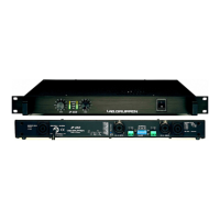
Rear panel
The following connectors are available on the rear panel:
1 ANALOG INPUTS and LINK - XLR-F input connectors provided for
each channel, with XLR-M link output connectors.
2 AES3 INPUT and LINK – AES3 digital inputs are on an XLR-F
connector with a link output on an XLR-M connector.
3 NETWORK (Ethernet) – An RJ45 jack is supplied for connection
to an Ethernet network for external control and monitoring, either by
a direct wired connection or via an external WiFi router to an iPad or
tablet. LEDs below the connector indicate valid network connection
(LINK) and network activity (ACT).
1 2
3 4
5
6
4 speakON OUTPUT CONNECTORS – Both channel outputs are
available on a four-pole connector at the left; either channel 1 or both
channels 1 and 2 may be connected. Only channel 2 is available on
the connector to the right.
5 BINDING POST CONNECTORS – Connectors for channel 1 and
channel 2.
6 AC LINE INPUT – A locking IEC receptacle accepts the AC line
input, 50 Hz or 60 Hz, 100 V – 240 V. Use an IEC cable with the proper
connector for country of use.