BTA 060, Rev 1K1 Page 15/18
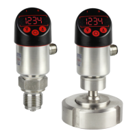
The switch-point (SP) must be between the upper range limit (URL) and the reset-point.
The reset-point (rP) must be between the lower range limit (LRL) and the switch-point. The
minimum distance between switch-point and reset-point (minimal hysteresis) is 0.5% of the
measuring range.
Figure 13: Setting ranges for switch-point and reset-point
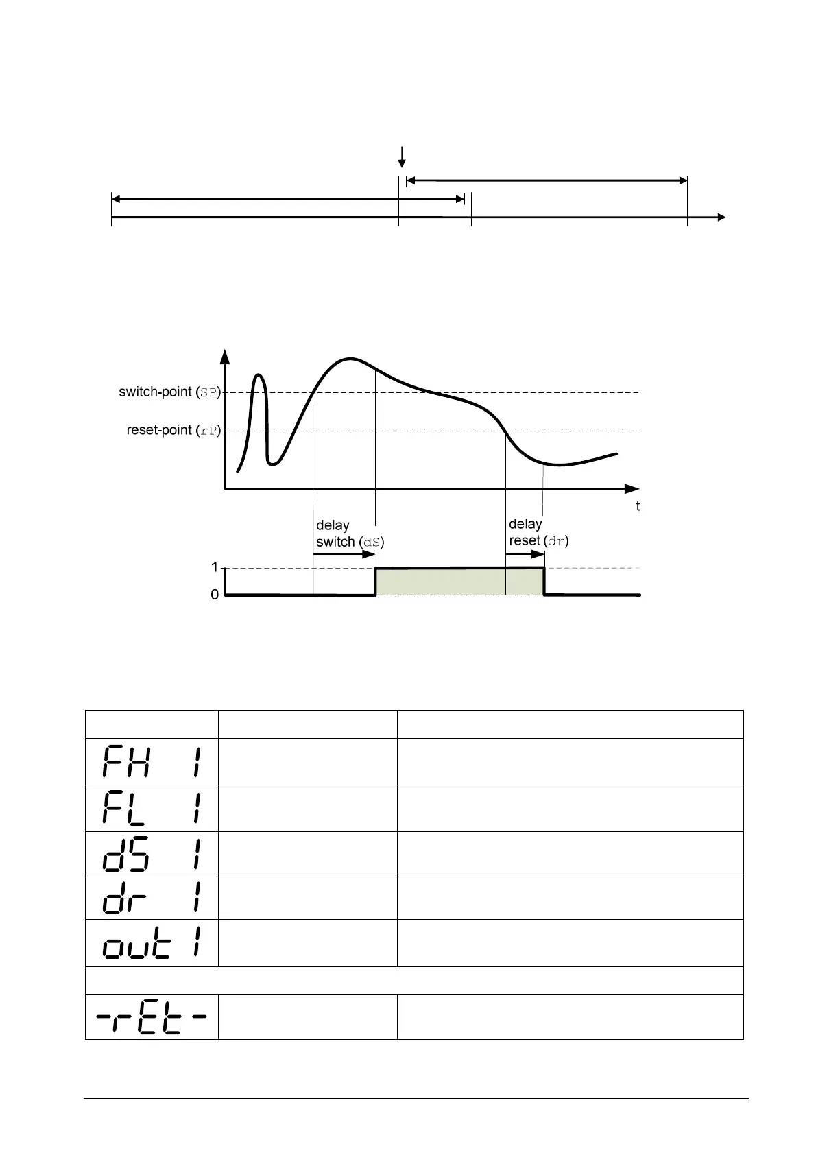
You can define delays for the switch-point as well as the reset-point, e.g. to avoid that
short pressure peaks trigger the switch.
Figure 14: Output delays for a hysteresis function normally open (Hno)
When you select a frame function, the menu items for switch-point and reset-point are
replaced by the upper and lower frame limits. The minimum difference of the frame limits is
also 0.5% of the measuring range.
Display Designation Description
Frame high Upper frame limit in the selected measuring
unit
Frame low Lower frame limit in the selected measuring
unit
Delay switch Output delay when entering the frame
Delay reset Output delay when leaving the frame
Output function Configuring the output (normally open /
normally closed, hysteresis / frame)
Menu items for second switch point
Return
Return to "SP"
Table 12: Menu items for a switching output with frame function
LRL
rP
SP
URL
0.5% of MR
Setting range for
the reset-point
Setting range for
the switch-point