BTA 060, Rev 1K1 Page 3/18
After the mechanical installation and the electrical connection are both complete, the
device is ready for use as soon as the voltage supply is switched on.
3.1 Electrical Connection
Make all electrical connections with the voltage supply switched off.
Permissible supply voltage U
V
= 14 - 30 VDC
Permissible load R
B
= (U
V
- 14 V) / 22 mA
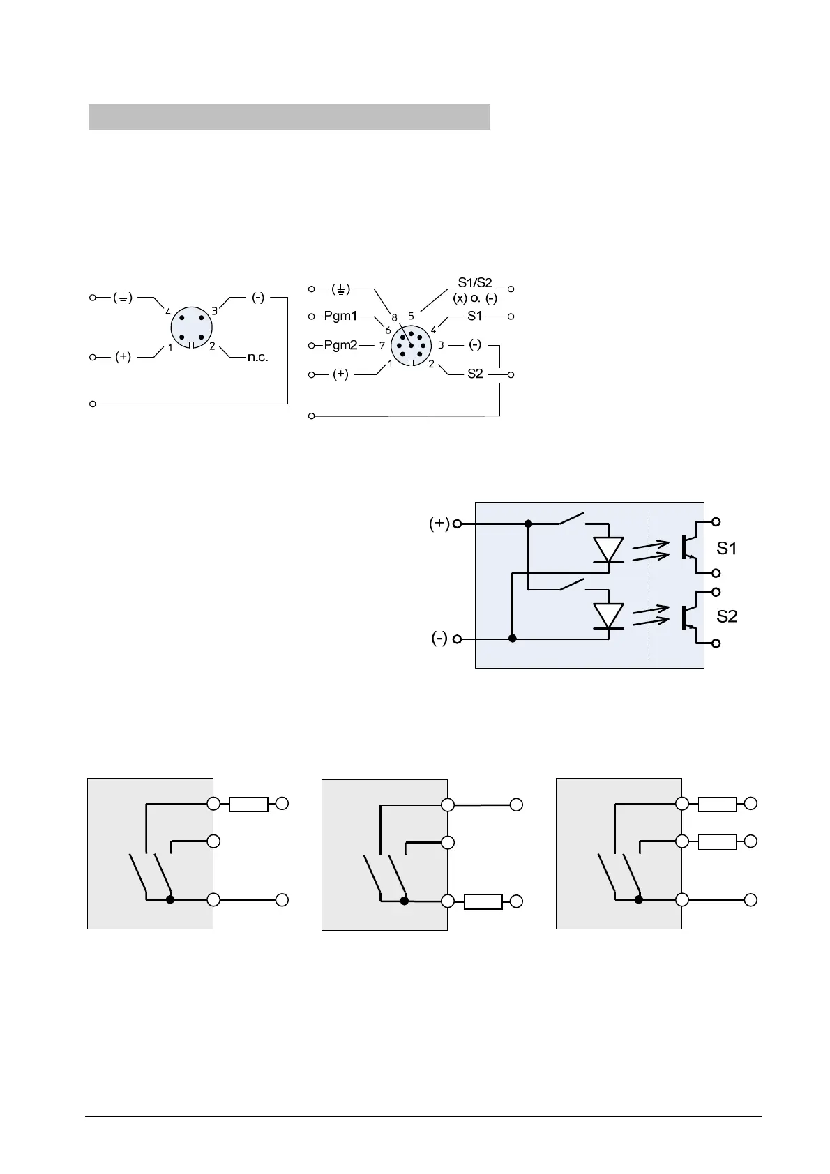
4-pole connector
8-pole connector (for switching
outputs)
Explanations
(+) plus-side of supply
(-) minus-side of supply
n.c. not connected
S1/S2 common pin of switching
outputs (see below)
S1 switching output 1
S2 switching output 2
Pgm1/2 programming pins
Figure 1: Pin assignment for M12 circular connector (device side)
3.1.1 Connecting the switching outputs (optional)
The switching outputs are potential-free.
They are electrically isolated from the
supply side (see Figure 2).
Therefore you can connect the load on the
high-side (PNP-style) or the low-side
(NPN-style) as long as you use only one
switching output.
Figure 2: Switching outputs isolated from supply
Due to the limited number of pins either the low-side or the high-side is combined internally
and routed to Pin 5. Therefore you have to connect both loads as shown below if you want
to use both switching outputs.
Figure 3: Connecting options with shared low-side