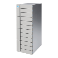
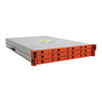
LaCie 12big Rack Network Table of Contents
User Manual page 2
3.4.2. Engaging the Drive Module Anti-tamper Locks .................................................................. 24
3.4.2.1. Activating the Locks .......................................................................................... 24
3.5. Power Down ............................................................................................................................... 25
4. Troubleshooting & Problem Solving .......................................................................... 26
4.1. Overview ................................................................................................................................... 26
4.1.1. Initial Start-up Problems .................................................................................................. 26
4.1.1.1. Faulty Cords .................................................................................................... 26
4.1.1.2. Alarm Sounds On Power Up .............................................................................. 26
4.1.1.3. Computer Doesn’t Recognize the LaCie 12big Rack Network Subsystem .............. 26
4.2. LED States .................................................................................................................................. 27
4.2.1. Power Supply Unit LEDs................................................................................................... 27
4.2.2. Ops Panel LEDs ............................................................................................................. 27
4.2.3. Cooling Fan LEDs ........................................................................................................... 28
4.2.4. Drive Carrier Module LEDs .............................................................................................. 28
4.2.5. Rear Panel LED .............................................................................................................. 28
4.2.6. ATX Server LEDs ............................................................................................................. 29
4.2.6.1. Status LEDs ...................................................................................................... 29
4.2.6.2. NIC LEDs ......................................................................................................... 29
4.3. Audible Alarm ............................................................................................................................ 30
4.4. Alarm Interpretation .................................................................................................................... 30
4.5. Troubleshooting .......................................................................................................................... 32
4.5.1. System Faults ................................................................................................................. 32
4.5.2. Power Supply Unit Faults ................................................................................................. 32
4.5.3. Cooling Fan Faults ......................................................................................................... 32
4.5.4. Thermal Monitoring and Control...................................................................................... 33
4.5.5. Thermal Alarm ............................................................................................................... 33
4.6. Drive Carrier Module Faults ......................................................................................................... 34
4.7. Dealing with Hardware Faults ...................................................................................................... 34
4.8. Continuous Operation During Replacement .................................................................................. 34
5. Module Replacement ................................................................................................. 35
5.1. Overview ................................................................................................................................... 35
5.2. ESD Precautions ......................................................................................................................... 35
5.3. Replacing a Module .................................................................................................................... 35
5.3.1. Power Supply Units ......................................................................................................... 36
5.3.1.1. Removing a Power Supply Unit........................................................................... 36
5.3.1.2. Installing a Power Supply Unit ............................................................................ 37
5.3.2. Cooling Fans ................................................................................................................. 38
5.3.2.1. Removing a Cooling Fan ................................................................................... 38
5.3.2.2. Installing a Cooling Fan .................................................................................... 39
5.3.3. Drive Carrier Module ...................................................................................................... 39
5.3.3.1. Removing a Drive Carrier .................................................................................. 39
5.3.3.2. Installing a Drive Carrier ................................................................................... 40
5.4. Replacing the SAS Expander PCB ................................................................................................. 41
5.5. Replacing ATX Motherboards ....................................................................................................... 42
5.5.1. Replacing FB-DIMM Memory Modules ............................................................................. 42
5.5.2. Replacing a CPU ............................................................................................................ 42
5.6. Replacing PCI Cards ................................................................................................................... 43
5.6.1. NVRAM Card ................................................................................................................. 43
5.7. Blanking Plates ........................................................................................................................... 43
5.8. Replacing RAID Controller PCI Cards ........................................................................................... 43
5.9. Replacing the Battery Backup Unit ................................................................................................ 43
5.10. Replacing the Boot Drives ............................................................................................................ 45