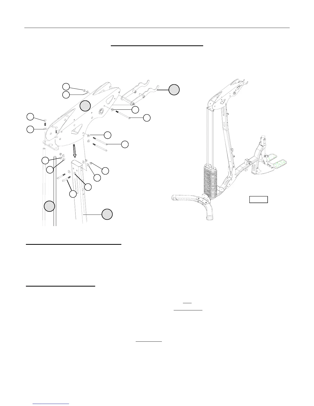
ASSEMBLY STAGE # 3
Attach Upper Pulley Housing to the Vertical Upright & Guide Rods
Assembly Hardware Required:
#37 Button Head Allen Screw Qty. 3 #50 Flat Washer Qty. 12
#40 Button Head Allen Screw Qty. 2 #55 Nylon Nut Qty. 5
#44 Button Head Allen Screw Qty. 2
Assembly Description: (2-Person Assembly is Recommended)
A) Align the associated mounting holes of the Upper Pulley Housing (#5) with the upper mounting holes of the
Vertical Upright (#4). Loosely fasten the assemblies in place using side mounting hardware; 2-Button Head Allen
Screws (#37), 4-Flat Washers (#50) and 2-Nylon Nuts (#55), back to front mounting hardware; 2-Button Head
Allen Screws (#40), 4-Flat Washers (#50), and 2-Nylon Nuts (#55).
B) Align the rear mounting holes of the Upper Pulley Housing (#5) with the Guide Rods (#19) and securely fasten the
assemblies together using 2-Button Head Allen Screws (#44) and 2-Flat Washers (#50). Assembly Note: After
securing the guide rod mounting, go back and fully tighten
the other mounting hardware.
C) Align the second-front mounting hole of Upper Pulley Housing (#5) with the bolt-through sleeve of the Lat Bar
Holder (#6) and secure the assemblies in place using 1-Button Head Screw (#37), 2-Flat Washers (#50), and
1-Nylon Nut (#55).
♦ Assembly Stage #3 completed (Reference Figure #5)
ASSEMBLY INSTRUCTION PAGE 10
37
6
5
50
55
50
44
50
40
50
55
50
37
50
4
19
Figure #5
50
55