A
SSEMBLY STAGE # 6
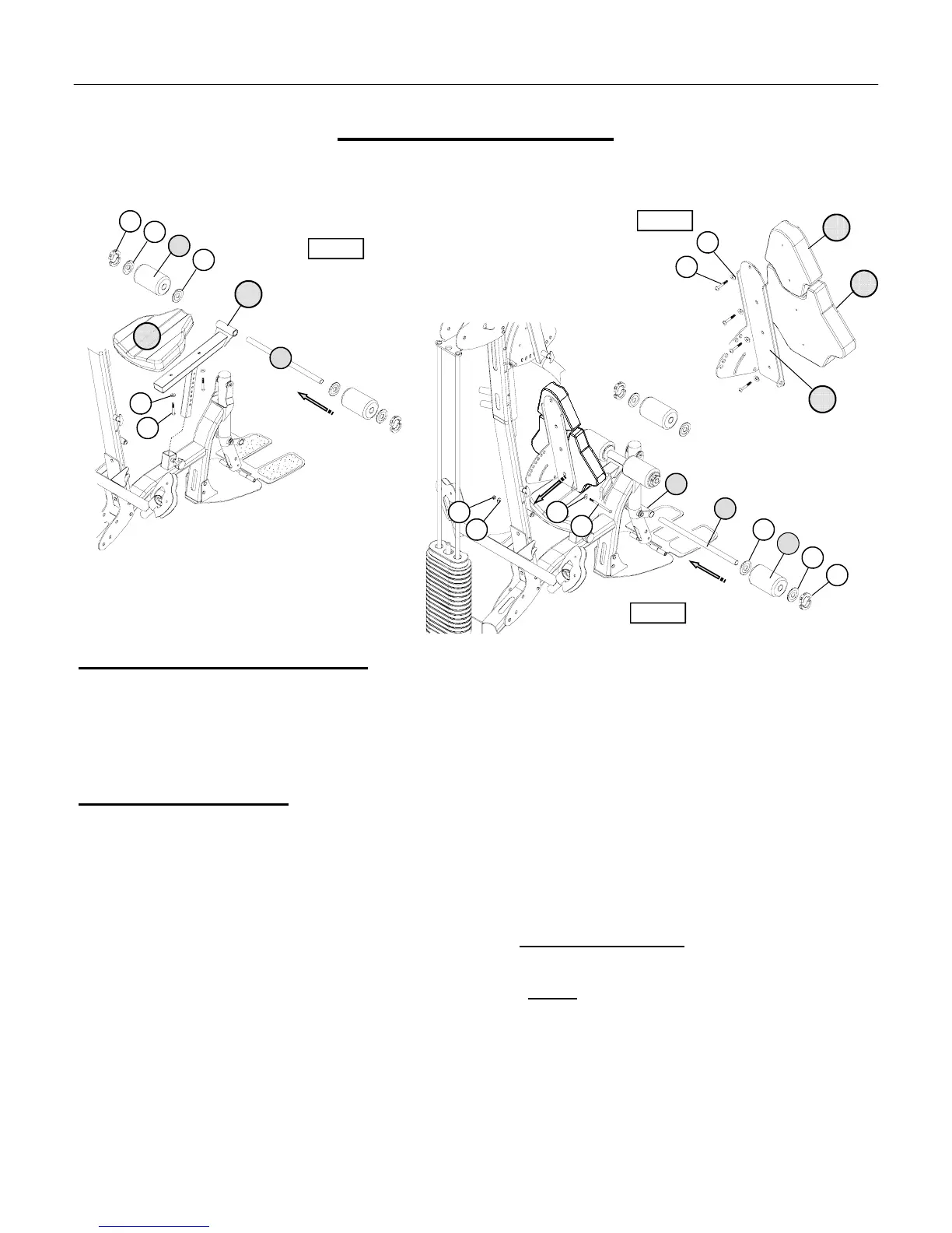
Attach Upholstery & Roller Pads to the Frame
Assembly Hardware Required:
#34 Button Head Allen Screw Qty. 1 #52 Flat Washer Qty. 6
#45 Button Head Allen Screw Qty. 2 #54 Nylon Nut Qty. 1
#46 Button Head Allen Screw Qty. 4 #56 Plastic Washer Qty. 8
#48 Flat Washer Qty. 2 #58 Split Collar
Assembly Description:
A) SECURELY fasten the Seat Pad (#61) to the Seat Adjustment Post (#10) using 2-Button Head Allen Screws
(#45) and 2-Flat Washers (#52). Slide the seat assembly into the insert of the Base Frame (#1) and use the
adjustment knob to lock the seat in a set position. (Reference Figure #7)
B) Slide a Roller Pad Tube (#18) through the front collar of the Seat Adjustment Post (#10) and assemble1-Roller
Pad (#60), 2-Plastic Washers (#56), and 1-Split Collar (#58) over each end of the tube
. (Reference Figure #7)
C) SECURELY fasten the Upper & Lower Back Pads (#62 & #63) to the Back Pad Mounting Plate (#22) using
2-Button Head Allen Screws (#46) and 2-Flat Washers (#52) per pad
. (Reference Figure #8)
D) Attach the Back Pad Mounting Plate (#22) to the Vertical Upright (#4) using 1-Button Head Allen Screw (#34),
2-Flat Washers (#48), and 1-Nylon Nut (#54). Assembly Note: Use the T-handle Pop-pin to select a back pad /
mounting plate position.
E) Slide the remaining Roller Pad Tube (#18) through the Lower Pivot (#11) and assemble 1-Roller Pad (#60),
2-Plastic Washers (#56), and 1-Split Collar (#58) over the each end of the tube. (Reference figure #8)
Assembly Stage #6 completed
A
SSEMBLY INSTRUCTION
62
22
61
10
58
52
60
56
56
56
18
56
63
60
58
Figure #7
Figure #8
45
54
48
46
52
18
48
34
Figure #7
11