ASSEMBLY STAGE # 4
Assemble R.O.M. &Press Arm Assembly to Upper Pulley Housing
Assembly Hardware Required:
#33 Button Head Allen Screw Qty. 1 #54 Nylon Nut Qty. 3
#48 Flat Washer Qty. 4 #57 Hardware Cap Qty. 2
#53 Cap Mounting Ring Qty. 2
Assembly Description:
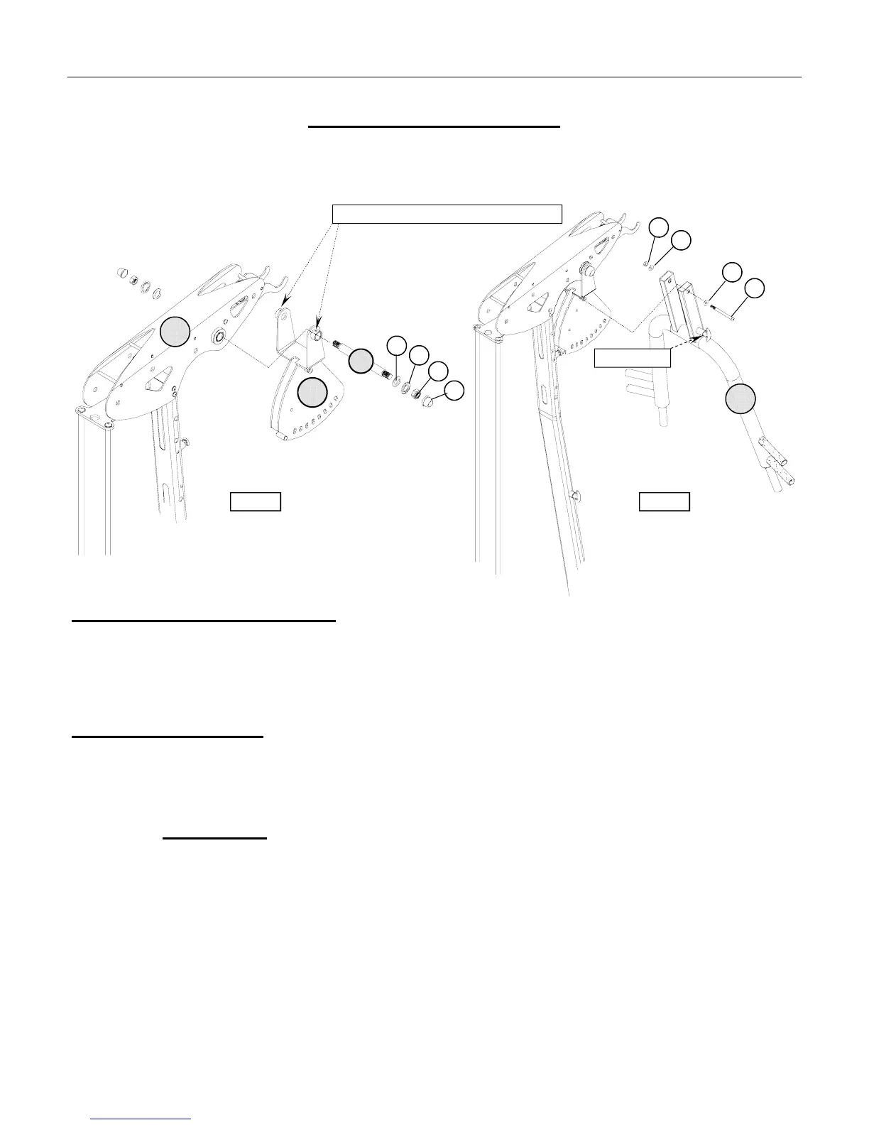
A) Align the pivot-boss of the Range of Motion Assembly (#8) with the shaft bearings of Upper Pulley Housing (#5)
and slide the Pivot Shaft (#27) through the both assemblies. Securely mount the shaft in place using 1-Flat Washer
(#48), 1-Cap Mounting Ring (#53), 1-Nylon Nut (#54), and 1-Hardware Cap (#57) onto each side. (Reference
Figure # ) Assembly Note: Once the Pivot Shaft is into position and properly aligned, securely tighten the set screws
on top of the pivot-boss of R.O.M
B) Pull out on t-handle pop-pin and guide the Press Arm Assembly (#9) into position over the R.O.M. Assembly (#8).
Allow the pop-pin to be positioned in one of adjustment holes of the R.O.M. Assembly. Align the upper mounting
holes of the Press Arm Assembly (#9) with middle pivot-boss of the R..O.M. Assembly and secure in place using
1-Buttom Head Allen Screw (#33), 2-Flat Washers (#48), and 1- Nylon Nut (#54). (Reference Figure # )
♦ Assembly Stage #4 completed
ASSEMBLY INSTRUCTION PAGE 11
27
8
67
53
57
54
5
Note: Tighten Set Screws to lock the Pivot Shaft in position
Figure #6 Figure #6
33
48
48
54
9
T-Handle Pop-Pin