ASSEMBLY STAGE # 1
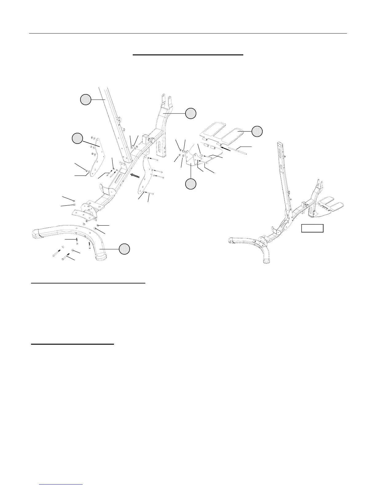
Attach Rear Stabilizer, Foot Plate, &Vertical Upright to Base Frame
Assembly Hardware Required:
#32 Carriage Bolt Qty. 2 #49 Curved Washer Qty. 4
#35 Button Head Allen Screw Qty. 2 #50 Flat Washer Qty. 12
#37 Button Head Allen Screw Qty. 6 #54 Nylon Nut Qty. 4
#40 Button Head Allen Screw Qty. 2 #55 Nylon Nut Qty. 8
#48 Flat Washer Qty. 2 #64 Pulley Spacers Qty. 2
Assembly Description:
A) SECURELY fasten the Rear Stabilizer (#17) to the Base Frame (#1) using back to front mounting hardware; 2-Button
Head Allen Screws (#35), 4-Curved Washers (#49), and 2-Nylon Nuts (#54) bottom to top mounting hardware; 2-Carriage
Bolts (#32), 2-Flat Washers (#48) and 2-Nylon Nuts (#54).
B) Loosely fasten the Foot Plate (#3) to the Base Frame (#1) using 2-Button Head Allen Screws (#37), 2-Pulley Spacers (#64),
2-Flat washers (#50), and 2-Nylon Nuts (#55).
C) Remove the 2- retaining rings positioned in the middle of the Hinge Pin (#28) Align the hinge mounting tabs of the Folding
(Foot) Plate (#7) with the Foot (Base) Plate (#3) and insert the Hinge Pin (#28) through both assemblies. Reinstall the 2-
reatinig rings, which will secure the alignment / position of the Hinge Pin and Foot Plate Assemblies.
D) SECURELY fasten the Vertical Upright (#4) to the Base Frame (#1) using 2-Side Brace (#21), 4-Button Head Allen
Screws (#37), 2-Button Head Allen Screws (#40), 12-Flat Washers (#50) and 6-Nylon Nuts (#55).
♦ Assembly Stage #1 completed (Reference Figure #1)
ASSEMBLY INSTRUCTION PAGE 8
32
48
49
50
50
49
35
54
54
55
50
40
50
37
55
Figure #1
7
3
1
4
17
37
50
28
64 55
50
55
64
37
21