43
8 Options
8 Options
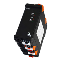
8.1 Analogue Outputs via LSB Module Current, alternative Voltage, LSB address 19
8.1.1 Functional Description
• Current module: 4 analogue outputs 0/4 ... 20 mA
• Voltage module: 4 analogue outputs 0/2 ... 10 VDC
• Possible to quickly wire several modules by means of strapping plugs
The LSB modules are universally applicable output modules, which are controlled via the LSB
SYSTEM BUS. In the process, the module is triggered by an adjustable address
(1 - 99). The statuses of the outputs are transferred in the data bytes. If an analogue output
module with the same address exists in the system, the voltage / current measured there is
shown on the respective output.
NOTICE
All outgoing lines from the LSB module must be shielded. The shields must be applied to the
PE rail as short as possible.
NOTICE
The termination resistor (120 ) must be installed and activated on the first and the last BUS
device.
Avoid stub line!