44
8 Options
8.1.2 Factory Setting of Analogue Outputs via LSB Module
The module is activated at the factory. In case of a later installation or exchange, the LSB ad-
dress 19 must be set on the module using only 2 rotary switches.
Analogue output 1 (O
2
measurement value)
• Setting range 0 … 25 % O
2
adjustable
• Factory setting: 0 … 10 Vol.% O
2
4 … 20 mA, fault 0 mA
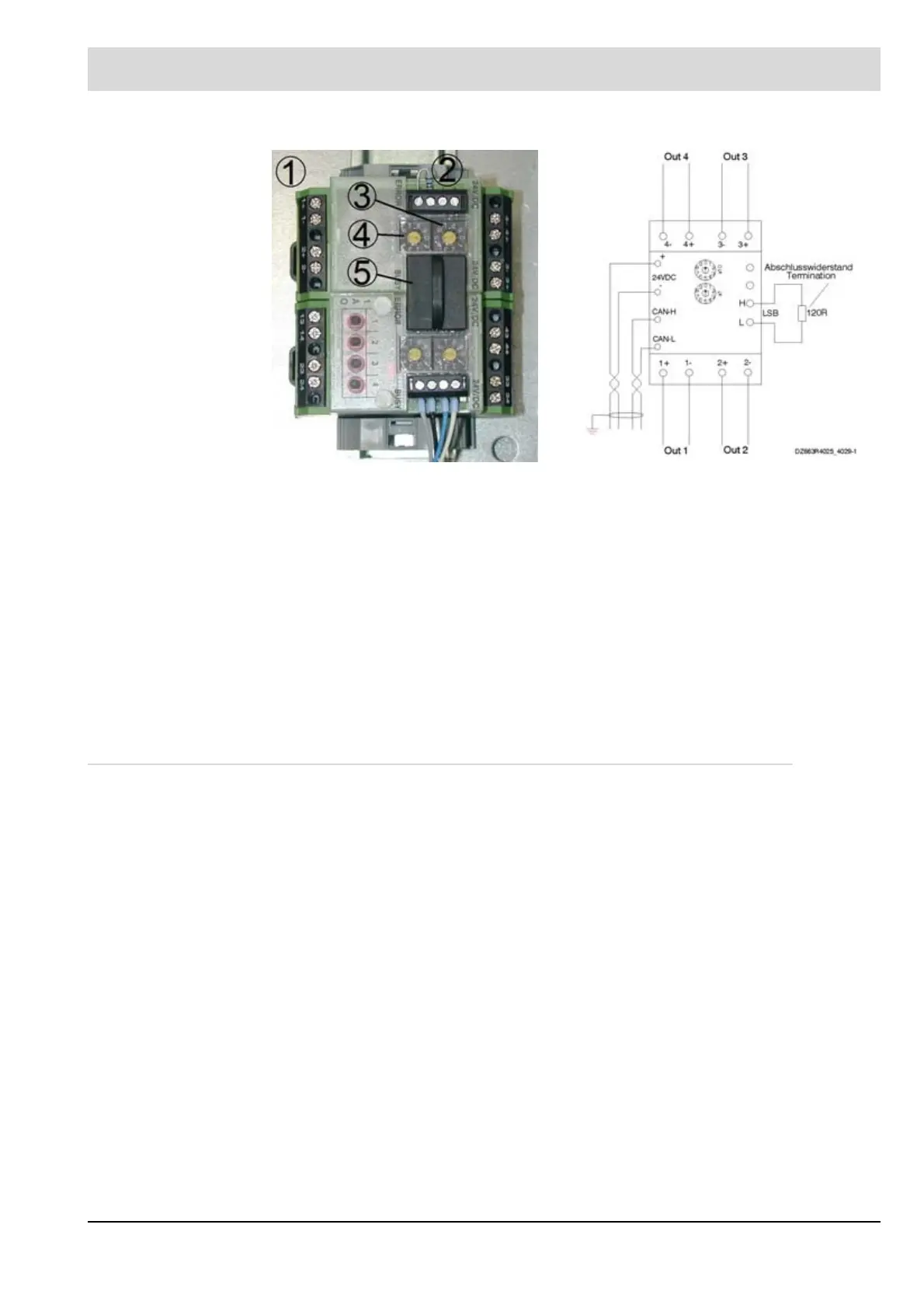
1 Analogue output module Terminal assignment:
2 LSB terminal resistance, 120 1+ / 1- Analogue output 1
3 Rotary switch for setting the tens
LSB address
2+ / 2- Analogue output 2
4 Rotary switch for setting the ones
LSB address
3+ / 3- Analogue output 3
5 Jumper plug 4+ / 4- Analogue output 4
24 VDC Voltage supply for LT3 Terminals
77-/78+
CAN H/L LAMTEC SYSTEM BUS for LT3
Terminals 74 H/75 L