PAGE 3
The control valve is compatible with a variety of regenerants and resin cleaners. The control valve is capable of routing
the ow of water in the necessary paths to regenerate or backwash water treatment systems. The injector regulates
the ow of brine or other regenerants. The control valve regulates the ow rates for backwashing, rinsing, and the
replenishing of treated water into a regenerant tank, when applicable.
The control valve uses no traditional fasteners (e.g. screws); instead clips, threaded caps and nuts and snap type latches
are used. Caps and nuts only need to be rmly hand tightened because radial seals are used. Tools required to service
the valve include one small blade screw driver, one large blade screw driver, pliers and a pair of hands. A plastic wrench
is available which eliminates the need for screwdrivers and pliers. Disassembly for servicing takes much less time than
comparable products currently on the market. Control valve installation is made easy because the distributor tube can
be cut ½” above to ½” below the top of tank thread. The distributor tube is held in place by an o-ring seal and the control
valve also has a bayonet lock feature for upper distributor baskets.
The AC adapter comes with a 15 foot power cord and is designed for use with the control valve. The AC adapter is for dry
location use only. The control valve remembers all settings until the battery power is depleted if the power goes out. After
the battery power is depleted, the only item that needs to be reset is the time of day; other values are permanently stored
in the nonvolatile memory. The control valve battery is not rechargeable but is replaceable.
COMPONENTS:
MODEL
MINERAL TANK
(dia. & ht.)
MIERAL-
(QUANTITY OF BAGS)
7-LETDAN-1B FG1047D, 10 X 47 (with dome plug) A8021 CALCITE - (2)
7-LETDAN-1.5B FG1054D, 10 X 54 (with dome plug) A8021 CALCITE - (3)
7-LETDAN-2B FG1348D, 13 X 48 (with dome plug) A8021 CALCITE - (4)
7-LETDAN-3B FG1365D, 13 X 65 (with dome plug) A8021 CALCITE - (6)
7-LETIM-1B FG1044,10 X 44 A8007 BIRM - (1)
7-LETIM-2B FG1348, 13 X 48 A8007 BIRM - (2)
7-LETIM-3B FG1465, 14 X 65 A8007 BIRM - (3)
7-LETCT-1B FG1044,10 X 44 A8009 CARBON - (1)
7-LETCT-2B FG1348, 13 X 48 A8009 CARBON - (2)
7-LETCT-3B FG1465, 14 X 65 A8009 CARBON - (3)
7-LETST-1B FG1044,10 X 44 A8014 FILTER AG - (1)
7-LETST-2B FG1348, 13 X 48 A8014 FILTER AG - (2)
7-LETST-3B FG1465, 14 X 65 A8014 FILTER AG - (3)
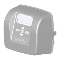
SERVICE
FROM W ELL PUMP
PRESSURE
TANK
IN
OUT
DRAIN
LINE
BYPASS SHOULD
BE PIPED IN IF
OPTIONAL BYPASS
VALVE IS NOT USED
TO 115V
RECEPTACLE
TOP VIEW
VALVES
BRINE
LINE
Click to buy NOW!
P
D
F
-
X
C
H
A
N
G
E
w
w
w
.
d
o
c
u
-
t
r
a
c
k
.
c
o
m
Click to buy NOW!
P
D
F
-
X
C
H
A
N
G
E
w
w
w
.
d
o
c
u
-
t
r
a
c
k
.
c
o
m
Allow one foot of clearance to service the valve. Place lter in desired location close to water supply inlet, after pressure
tank, and near a source for waste water, (utility sink, oor drain or sewer line). A 115/120V, 60Hz uninterrupted outlet is
required. Keep lter far enough away from walls and other obstructions to allow enough room for servicing the unit. If a
water softener is also to be installed, generally it will be placed in line after the neutralizer or lter.
From water supply→ neutralizer → lter → softener → to service
Minerals must be added to the lter. Add the mineral by following these
steps:
• Mineral can be loaded via the 1-1/4” dome hole using a funnel if the
system purchased has this feature or through the 2-1/2” opening on
the top of the mineral tank.
• If loading from the top of the mineral tank, remove the control valve by
turning counter-clockwise.
• Plug or tape the distributor tube. (Figure A)
• Add the mineral. Do not overll. Leave a minimum of 10” at the top of
the tank. (Figure B)
• Remove the plug or tape.
• Water can be manually added at this time to begin the soaking
process.
INSTALLATION