PAGE 8
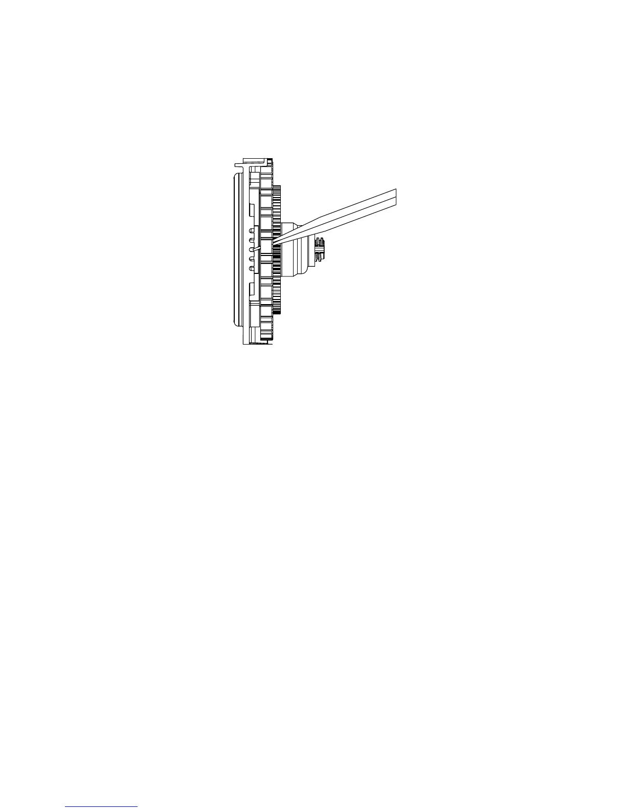
INJECTOR CAP, SCREEN, INJECTOR PLUG AND INJECTOR:
The screen, injector and/or injector plug(s) are installed under the injector cap in an easy to access location on top of the
valve. The injector cap contains four slots so no water accumulates in the cap. The injector cap is designed to be hand
tightened.
Under the injector cap there is an easy to clean removable screen to prevent fouling of the injector. There are two holes
under the injector cap labeled “DN” and “UP”. The holes will be lled with a plug or an injector.
The plug (Order # V3010-1Z) prevents water from traveling a certain pathway. The injector lets water pass through the
pathway. The self-priming injector increases the velocity of the water, creating a zone of negative pressure that draws in
the concentrated liquid regenerant, such as sodium chloride (brine), potassium permanganate, etc. The regenerant blends
with the stream of water, which passes through the media to regenerate the bed.
The injector provides a consistent regenerant/water mixture ratio over the entire operating pressure range of the control
valve. The injector provides good performance in a variety of applications, which may involve elevated drain lines and
long regenerant draw lengths. Injectors are chosen by knowing the type, amount, and regenerant ow rate for a particular
type of media. Guidelines can be found in the media manufacturer’s literature. The color coded injectors give different
regenerant draw, slow rinse and total ow rates over the pressure range.
NOTE: It is not recommended to eld convert valves from upow to downow and vice versa. Separate areas in the valve
supply water to the injector for upow and downow valves.
DRIVE CAP ASSEMBLY, MAIN PISTON AND REGENERANT PISTON:
The drive gears turn the main gear of the drive cap assembly, which moves the piston. The screw-driven, horizontally
moving piston stops at specic positions to direct the ow of water to backwash, regenerate, rinse or rell. The PC board
determines the position of the piston by counting pulses produced when the piston is moved. An optical sensor looking
at one of the reduction drive gears generates these pulses. Each cycle position is dened by a number of pulses. The
counter is zeroed each time the valve goes to the service position. The PC board nds the service position by noting the
increase in current delivered to the motor when the mechanical stop at the service position is reached. This method of
controlling piston position allows for greater exibility and requires no switches or cams (U.S. Patent 6444127).
A regenerant piston must be attached to the main piston.
SPACER STACK ASSEMBLY:
The spacer stack assembly provides the necessary ow passage for water during the different cycles. The all-plastic
spacer stack assembly (U.S. Patent 6402944) is a one-piece design which allows the stack to be removed using your
ngers.
The exterior of the stack is sealed against the body bore with self lubricating EPDM o-rings, while the interior surface is
sealed against the piston using slippery self cleaning directional (one-way) silicone lip seals. The lip seals are clear in
color and have a special slippery coating so that the piston does not need to be lubricated.