7
Read This Manual
This manual was developed by Lancer Worldwide as a reference guide for the owner/operator and installer
of this unit. Please read this manual before installation and operation of this unit. Please see pages 10-12 for
troubleshooting or service assistance. If this does not resolve the issue and you need additional assistance,
please call your Service Agent or Lancer Customer Service. Always have your model and serial number avail-
able when you call.
INSTALLATION
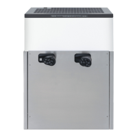
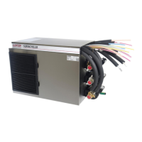
Unpacking the Chiller
Selecting/Preparing a Counter Location
1. Remove top portion of carton by lifting up.
2. Remove top inner carton pad and corners.
3. Lift unit up by plywood shipping base and remove lower
portion of carton.
4. Remove plywood shipping base from unit by moving unit so
that one side is o the countertop or table allowing access
to screws on the bottom of the plywood shipping base.
Inspect unit for concealed damage. If evident, notify
deliveringcarrierandleaclaimagainstthesame.
NOTE
If unit is to be transported, it is advisable to leave the
unit secured to the plywood shipping base.
NOTE
DO NOT LAY UNIT ON ITS SIDE OR BACK.
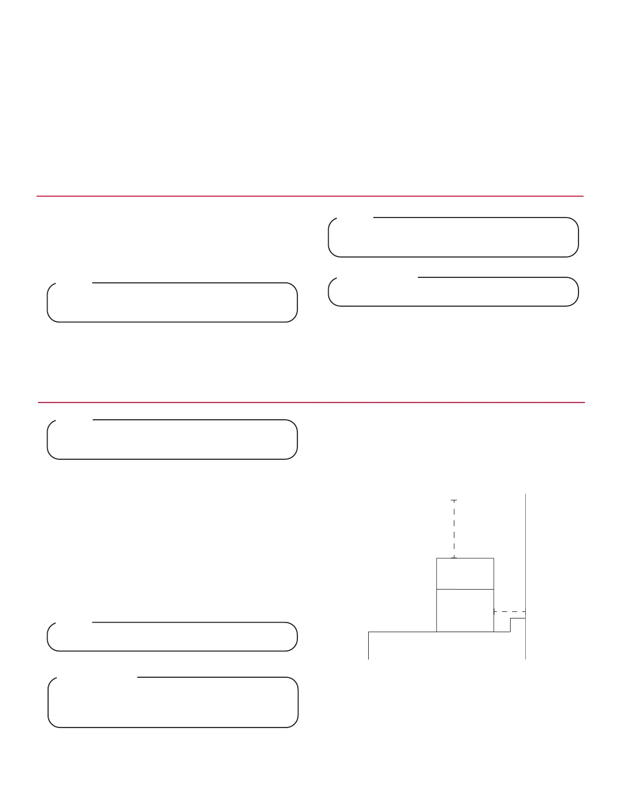
! ATTENTION
Failuretomaintainspeciedclearancewillcausethe
compressor to overheat and will result in compressor
failure.
! ATTENTION
6”
15”
1. The chiller is designed to sit on a at, supported surface
capable of supporting a minimum weight of 500 lbs (227
kg). Select a location that is in close proximity to a prop-
erly grounded electrical outlet that meets the requirements
shown in the Specications section found on pages 4-5.
2. Select a location for the syrup pumps, CO
2
tank, syrup
containers, water lter (recommended), and remote
carbonator. Please see General System Overview on page
6 for reference.
3. When the chiller is to be permanently bolted to the counter-
top, use sealant to seal chiller base to countertop.
4. Condenser air is drawn in from the back grill located on the
bonnet and discharged out the top of the bonnet. A mini-
mum clearance of 15 inches (380 mm) over the top and a
6 inches (152 mm) behind the unit must be maintained to
provide for proper air ow and circulation.
NSF listed units must be sealed to the counter.
NOTE
The chiller should only be installed in a location where
it can be overseen by trained personnel.
NOTE
5. To mount the chiller in the designated location, cut the nec-
essary holes in the countertop.