4
8. Route appropriate tubing from the water source to the
carbonator pump inlet at the unit, and connect tubing to
water source.
11. Using a conductivity meter, measure the electric conductivity
of the distilled water mixture.
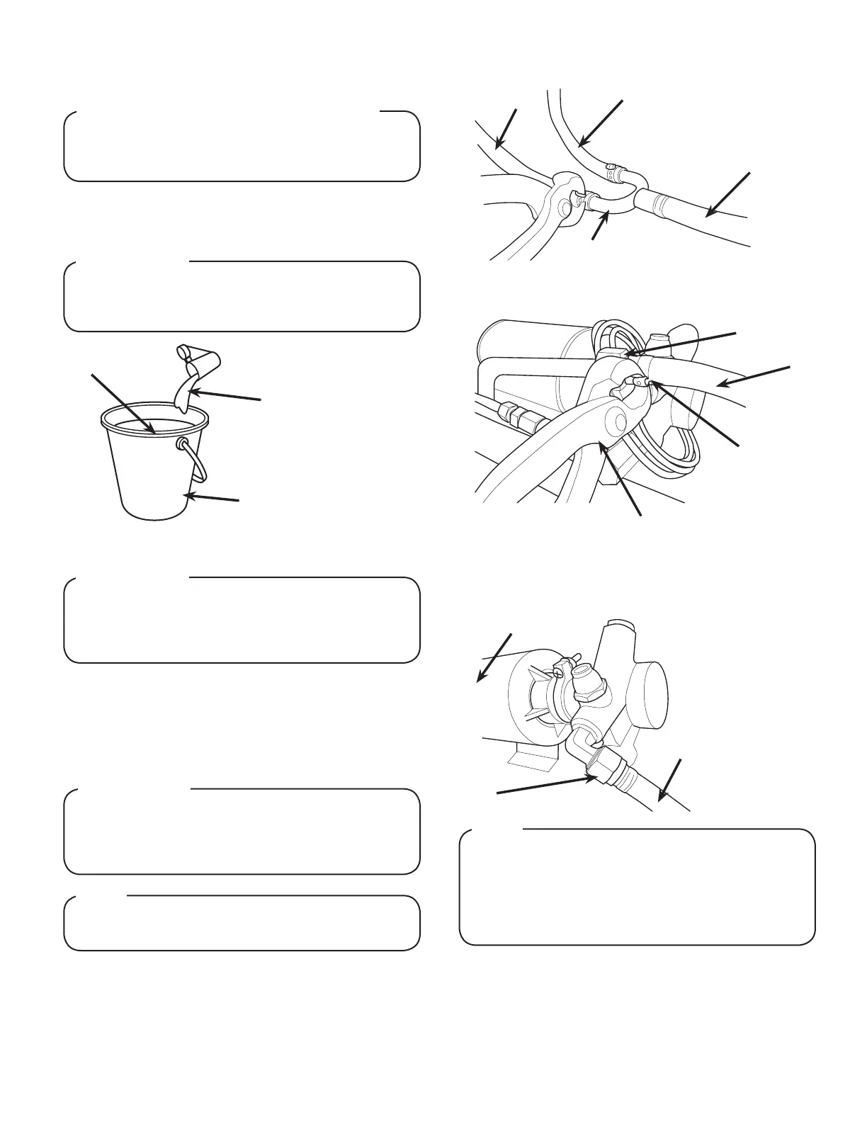
9. Insert water line into a large bucket, and ll with approx. 5.4
gallons (20.4 L) of distilled water.
10. Add 1/8 oz (4 g) of baking soda to distilled water and stir.
12. Remove yellow cap from the water bath ll hole and insert
and insert a funnel into the ll hole.
13. Carefully pour the distilled water mixture into the water bath
tank until water ows out of the overow tube at the front
of the unit. Then replace yellow cap (Repeat steps 7-8 if
needed)
Carefully read this before lling the water bath tank.
In order to optimize the maximum performance of the
dispenser, the following MUST be adhered to:
! CRITICAL - to maximize performance
A
C
A. Bucket
B. Distilled Water
(Approx. 5.4 gal)
C. Baking Soda
(Approx. 1/8 oz)
14. Using tubing cutters, cut water supply line and install “U”
tting, (PN 01-2128/01).
The E.C. measurement of the distilled water mixture
must be between 100 and 500 uS/cm. Below 100 uS/cm,
the compressor will not work properly and above 500
uS/cm could cause the lines to freeze.
! ATTENTION
The water bath compartment must be lled with water
before plugging in the unit, otherwise the compressor
fan may not operate properly. DO NOT use RO or
puried water.
! ATTENTION
15. Route appropriate tubing from the plain water inlet, located
at the front of the unit, to one side of the “U” tting at water
supply and connect tubing to inlet.
Make sure the top of overow tube is not covered so
that the water from the water bath tank cannot escape.
NOTE
A
B
C
A. Line to Water Source
B. Line To Plain Water Inlet
C. Line To Carb Water Inlet
D. “U” Fitting
D
16. Route appropriate tubing from the carbonator pump inlet and
the “U” tting at water supply then connect tubing to inlet
using are seal washer (PN 05-0017). Use a back-up wrench
to prevent damage to carbonator pump.
A
B
C
A. Plain Water Inlet
B. Plain Water Line
C. Oetiker Pliers
D. Fitting
D
If the water source is above 50 psi (0.345 MPa), cut
tubing assembly and install Water Regulator Kit (PN
18-0253/02, sold separately) as shown in kit instruction
sheet. Once installed, use a test gauge assembly (PN
22-0138, sold separately), to set regulator at a
maximum of 50 psi (0.345 MPa).
NOTE
A
B
C
A. Carbonator
B. Carb Water Inlet
C. Carb Water Line
D. Fitting
For proper function of the electronic ice bank control
the total dissolved solids (TDS) measurements should
be 100-500 ppm.
B
! ATTENTION