6
Dispenser Setup
1. Purge water to ll carbonator tank by opening carbonator
relief valve. Close relief valve once water comes out.
A. Relief Valve (Open)
B. CO
2
Inlet
C. CO
2
Line
A
B
C
2. Activate each valve until a steady ow of water is achieved.
3. Turn power o.
4. Unplug the Pump Motor Connector from the control box. Use
the wiring diagram either on the unit control box or in the
back of this manual for reference.
Pump Motor will run for a few seconds to ll carbonator
tank
NOTE
Failure to disconnect the motor power supply will
damage the carbonator motor, the pump and void the
warranty.
! ATTENTION
5. Turn on CO
2
at the source then, using a screwdriver, adjust
the high pressure regulator at the source to 110 psi (0.758
MPa) then tighten locknut with wrench.
6. Adjust both of the low pressure regulators on the regulator
manifold to 75 psi (0.517 MPa) then tighten locknut with
wrench.
7. Activate each valve until gas-out is achieved.
8. Plug the Pump Motor Connector back into the control box.
A. Regulator Adjustment Screw
B. Adjust to 75 psi (0.517 MPa)
C. Wrench
A
B
C
9. Turn power on.
10. Activate each valve until a steady ow of carbonated water is
achieved.
Adjust Water Flow Rate & Syrup/Water Ratio
1. Close syrup shut-o at mounting block for rst valve.
2. Using a Lancer brix cup verify water ow rate (5 oz. in 4
sec.). Use a screwdriver to adjust if needed.
A
B
A. Plain Water ON
B. Syrup Closed
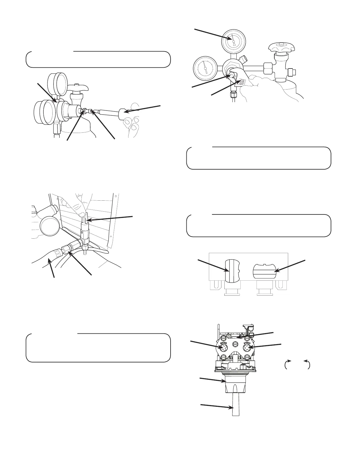
6. Using a wrench, loosen lock nut on the regulator adjustment
screw of the high pressure CO
2
regulator connected to the
source, then using a screwdriver back out lock nut screw all
the way.
DO NOT TURN ON CO
2
SUPPLY AT THIS TIME
! WARNING
A. CO
2
Regulator
B. Screwdriver
C. Loosened Lock Nut
D. Regulator Adjustment Screw
A
B
C
D
7. Repeat Step 6 for both low pressure CO
2
regulators on the
regulator manifold routed to the unit and the syrup pumps.
A
B
Increase Decrease
C
A. Flow Control, Water
B. Flow Control, Syrup
C. Nozzle (Diuser inside)
D. Mounting Block (not shown)
E. Soda Lever
D
E
Do not set ow rates or dispense from the unit until
after a complete ice bank is established.
NOTE