EasyManua.ls Logo

Laney TFX3 - User Manual

Laney TFX3
7 pages
Print Icon
To Next Page IconTo Next Page
Loading...
Newlyn Road, Cradley Heath, West Midlands. B64 6B£
www.laney.co.uk
Laney
Classic British Amplification
TFX3
Service InformationService Information
Question and Answer IconNeed help?

Do you have a question about the Laney TFX3 and is the answer not in the manual?

Overview

This document provides service information for the Laney TFX3, a classic British amplification guitar amplifier. It includes schematics for the preamp, output stage, and FX control board, along with a comprehensive bill of materials.

Function Description

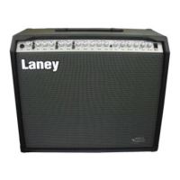
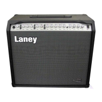
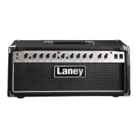
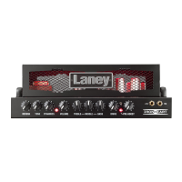
The Laney TFX3 is a 120W guitar amplifier designed for a range of tones, from clean to overdriven, with integrated effects. The amplifier features a multi-stage preamp, a robust output stage, and a digital effects (DSP) module for various sound enhancements.

The preamp section (TFX2/TFX3 PREAMP ASSY, part number 007985) is designed to shape the core tone. It includes multiple gain stages, tone controls (Treble, Mid, Bass), and separate channels for "Clean" and "Drive." The "Drive" channel offers additional gain and saturation, with controls for "Drive 1" and "Drive 2" levels, allowing for a wide spectrum of distorted sounds. A "Bright On/Off" switch is available to add high-frequency sparkle to the tone. A "HUM TRIM" adjustment is present, likely for minimizing unwanted noise in the preamp.

The output stage (TFX3 OUTPUT PCB ASSY, part number 007989) is responsible for amplifying the processed signal to drive a loudspeaker. It utilizes SAP16N and SAP16P power devices, configured in a push-pull arrangement, to deliver 120W of power. A "BIAS ADJ" (VR2) control allows for fine-tuning the quiescent current of the output transistors, which is crucial for optimal performance and longevity. The output section also includes protection circuitry, such as fuses and diodes, to safeguard the amplifier. An "Extension Loudspeaker" output (SK4) is provided, allowing connection to an external speaker cabinet.

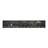
The FX control board (TFX3 FX CONTROL PCB ASSY, part number 007987) manages the integrated digital effects. It interfaces with a DSP module (HD1) and provides controls for "Clean FX Program," "Drive FX Program," "Clean Reverb Level," and "Drive Reverb Level." The "FX SEND" and "FX RETURN" jacks (SK2, SK3) allow for external effects processors to be integrated into the signal chain, offering flexibility in sound customization. The "OFFSET ADJ" (VR1) on the FX return path is likely used to balance the signal levels.

A footswitch (TFX4 FOOTSWITCH) is provided for remote control of key amplifier functions, including "CLEAN," "DRIVE1," "DRIVE2," and "FX." This allows musicians to switch between different channels and engage/disengage effects during live performance. The footswitch connects to the amplifier via a 4W loom.

Important Technical Specifications

  • Power Output: 120W
  • Mains Voltage: 230V (T2A fuse) or 115V (T5A fuse)
  • Power Devices: SAP16N, SAP16P (output stage)
  • Preamp Valves (Tubes): ECC83 (TFX2/TFX3 TUBE PCB ASSY, part number 007991)
  • Capacitors: Various types and values, including electrolytic (e.g., 4700uF 63V, 470uF 16V), polyester (e.g., 220nF 63V, 330nF 63V), ceramic (e.g., 47pF 50V, 100nF 50V), and film (e.g., 220nF 250V).
  • Resistors: Various types and values, including 0.25W, 0.5W, 2.5W, and 5W flame-proof resistors.
  • Semiconductors:
    • Transistors: 2N3819, MPSA42/43, MPSA92/93
    • Diodes: 1N4148, 1N4007, 3V9 Zener, 15V Zener
    • Integrated Circuits: 34072 (SMD TL072), 7805 (voltage regulator)
  • Connectors: IEC inlet for mains, mono jack sockets for input, FX send/return, and loudspeaker outputs, IDC PCB plugs, and various pin headers.
  • Controls:
    • Preamp: Gain, Treble, Mid, Bass, Drive 1, Drive 2, Clean Volume, Drive Volume, Bright On/Off, Vibe On/Off, Mute.
    • FX Control Board: Clean FX Program, Drive FX Program, Clean Reverb Level, Drive Reverb Level.
    • Output Stage: Bias Adjust (VR2), Offset Adjust (VR1).
  • Footswitch: 4-button footswitch for Clean, Drive1, Drive2, and FX.

Usage Features

The TFX3 is designed for versatile use by guitarists. The separate Clean and Drive channels, along with their respective volume and tone controls, allow for quick changes between different sonic textures. The "Bright On/Off" switch provides an instant tonal modification for brighter or warmer sounds. The "Vibe On/Off" and "Mute" functions offer additional control over the amplifier's output.

The integrated digital effects, controlled via the FX control board, provide a range of built-in sounds, enhancing the amplifier's capabilities without the need for external pedals. The "FX SEND" and "FX RETURN" loop allows for the integration of preferred external effects pedals or rack units, offering further customization of the sound.

The footswitch connectivity is a key feature for live performance, enabling seamless switching between channels and effects without interrupting playing. The "Extension Loudspeaker" output allows for connecting to larger or different speaker cabinets, providing flexibility for various venues and sound preferences.

Maintenance Features

The service information provides critical details for maintenance and repair.

  • Bias Adjustment (VR2): This is a crucial maintenance feature for the output stage. The note specifies: "Set VR2 to give 20mV across TP1 and TP2. Refer to service manual before adjusting bias preset." This ensures the output transistors operate efficiently and prevents premature failure.
  • Offset Adjustment (VR1): For the FX return path, the note states: "Set VR1 to give 0mV across LS+, LS-." This adjustment helps to balance signal levels and prevent DC offset issues.
  • Safety Critical Components: Components marked with a square symbol (☐) are identified as "safety critical component" and "MUST only be replaced with approved type." This highlights the importance of using specified parts to maintain safety standards. Flame-proof resistors (FP) are also noted as "Must only be replaced with same type and rating."
  • Fuse Replacement: The mains fuse (F1) is specified as T2A for 230V operation and T5A for 115V operation. Proper fuse replacement is essential for protection against overcurrents.
  • Modular Design: The amplifier is constructed with several distinct PCBs (Preamp, Output, FX Control, Tube PCB), which simplifies troubleshooting and component replacement.
  • Test Points (TP1, TP2): These are provided in the output stage for convenient measurement during bias adjustment.
  • Component List: The comprehensive bill of materials (BOM) includes part numbers, descriptions, and quantities for all components, facilitating accurate ordering and replacement of parts.
  • Schematic Diagrams: Detailed schematics for the preamp, output, and FX control boards provide a clear understanding of the circuit design, aiding in fault diagnosis.
  • Transformer Specifications: The mains transformer (TF300 230V MAINS TRANSFORMER, part number 006132) provides various secondary voltages, including ~8V for the 5VDC supply, ~200V for the tube PCB, and ~12V for the tube PCB, as well as +45V and -45V for the output stage.
  • Tube PCB: The TFX2/TFX3 TUBE PCB ASSY (part number 007991) indicates the presence of vacuum tubes (ECC83 VALVE STANDARD, part number 005548) in the preamp section, which may require periodic replacement.
  • Footswitch Wiring: A dedicated wiring diagram for the TFX4 footswitch is included, which is useful for troubleshooting footswitch-related issues.

Laney TFX3 Specifications

General IconGeneral
BrandLaney
ModelTFX3
CategoryMusical Instrument Amplifier
LanguageEnglish

Related product manuals