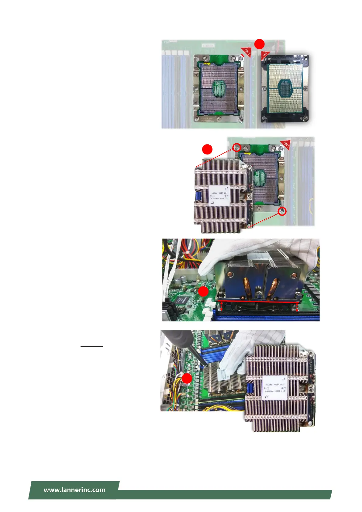
2. Flip the PHM over to align PIN1 of
the carrier with the Cutout of the
bolster plate.
3. Flip the PHM over, so the package
land of the processor will face the
socket. Lower the PHM vertically to
engage it to the alignment pins of
the bolster plate.
4. Make sure the PHM is sitting
horizontally on the bolster plate.
5. Use a torque driver to tighten the
four nuts to 12 in-lbf into the bolster
plate following the sequence
indicated on the heat sink (#1
#2#3#4).