Do you have a question about the Lanner NCA-1516 and is the answer not in the manual?
Explains document conventions, font types, and icons used for clarity.
Provides access to additional documentation and software updates via Lanner Download Center.
Provides a link to submit support tickets for technical assistance.
Email address for providing feedback, comments, or reporting errors.
Contact details for Lanner Electronics Inc. Taiwan headquarters.
Contact details for Beijing L&S Lancom Platform Tech. Co., Ltd.
Contact details for Lanner Electronics Inc. USA office.
Contact details for Lanner Europe B.V.
Contact details for Lanner Electronics Canada Ltd.
Details FCC compliance, interference, and cautions for modifications.
Notes on 5GHz band restrictions and overall FCC rule adherence.
Warns about explosion risk with incorrect battery types and proper disposal.
Guidelines for adequate air circulation and securing the chassis cover.
Precautions for handling equipment to prevent electrostatic discharge damage.
Precautions for rack-mount installations regarding flammables, specialists, and environment.
Importance of proper grounding and disconnection procedures for electrical safety.
Steps for connecting the grounding cable to the DC power source.
Requirement for grounding and connecting to an earthed socket-outlet.
Compliance for IT rooms according to NEC and NFPA 75.
Specifies restricted access location usage and skilled person installation.
Lists the items included in the product package.
Details available optional kits for the NCA-1516.
Information regarding SKUs and their main features for ordering.
Covers form factor, platform, BIOS, system memory, and networking specs.
Details LOM, I/O, storage, and expansion interface specifications.
Covers cooling, environmental, dimensions, power, and compliance specs.
Describes the SIM card slot and number of slots.
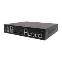
Explains the function of various LED indicators on the front panel.
Identifies the SMA connectors for LTE modules on the front panel.
Details power switch, reset button, and DC jack.
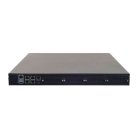
Covers console, USB, SFP, and LAN ports.
Details antenna ports and PoE expansion port.
Illustrates data flow and component layout on the motherboard.
Details pin assignments for FAN, SIM, CPLD, and 5G module connectors.
Provides pinout details for FAN, SIM, CPLD, and 5G module connectors.
Pinouts for 5G module selection and debug port headers.
Pinouts for 5V power connector and Gasp board header.
Pinouts for ME Recover Mode and SPI ROM burning headers.
Pinouts for Dying Gasp module, RTC, and CMOS headers.
Pinouts for PoE+ and Dying Gasp board header 2.
Pinouts for DC-IN adapter, case open switch, and button cell headers.
Precautions for personal injury, shock, and equipment damage during installation.
Overview of M.2 and mPCIE slots for wireless connectivity modules.
Instructions for unscrewing the chassis to open it.
Steps to pull open and lift the chassis cover.
Identifying the M2_1 slot for storage module installation.
Aligning module notches and inserting into the socket at an angle.
Securing the installed module with a provided screw.
Identifying the system memory slot for DIMM installation.
Aligning DIMM notch and inserting into the slot.
Pressing the DIMM vertically until it clicks into place.
Identifying the M.2 slot for LTE or WiFi module installation.
Aligning M.2 card notch and inserting into the slot.
Fixing the M.2 card with a dedicated screw.
Identifying the mPCIE slot for WiFi module installation.
Aligning mPCIE card notch and inserting into the slot.
Fixing the mPCIE module with a screw.
Lists the items included in the PoE Module Kit.
Steps to power off the system and open the chassis cover.
Locating the slot and replacing screws with standoff studs.
Aligning the power source pin and inserting the connector pins.
Securing the PoE module board with screws.
Connecting the power source pin to the power adapter.
Loosening screws and removing the SIM slot cover.
Pushing the SIM card into the slot until it clicks.
Using a fingertip to push and eject the SIM card.
Inserting the SMA female bulkhead through the panel antenna hole.
Attaching washer and nut, then tightening with a torque wrench.
Warning against using incorrect tools for fastening SMA connectors.
Table showing antenna placement for different SKU/modules (LTE, 5G, WiFi).
Recommended antenna placement for a single LTE module on the rear panel.
Recommended antenna placement for dual LTE modules on the rear panel.
Antenna placement for LTE modules on front and rear panels.
Antenna placement for 5G modules on front and rear panels.
Recommended antenna placement for one WiFi 5 (Wave 1) module.
Recommended antenna placement for one WiFi 5 (Wave 2) module.
Recommended antenna placement for one WiFi 6 module.
Antenna placement for one LTE and one WiFi 5 (Wave 1) module.
Antenna placement for one LTE and one WiFi 5 (Wave 2) module.
Antenna placement for one LTE and one WiFi 6 module.
Antenna placement for one 5G and one WiFi 5 (Wave 1) module.
Lists the items included in the rack-mount kit.
Instructions for attaching ear brackets to the chassis side panel.
Securing the adapter onto the holder with brackets and screws.
Attaching the adapter holder to the system's left side.
Securing the adapter's cable onto the adapter holder.
Introduction to BIOS firmware and steps to enter setup.
Explains the control keys for navigating and interacting within the BIOS setup.
Shows the main BIOS screen with version and copyright information.
Details how to set the system date and time in the BIOS.
How to navigate to the Advanced menu in the BIOS setup.
Lists available configuration options within the Advanced menu.
Configuration for TPM device support and PCR banks.
Setting the TPM 2.0 UEFI Specification version.
Manages security device support and PCR banks.
Configures pending operations and hierarchies for TPM.
Sets TPM UEFI Spec Version, Interface Type, and Device Selection.
Accesses parameters for serial port configurations (COM1, COM2).
Enables or disables Serial Port 1 (COM1).
Displays IO and IRQ settings for Serial Port 1.
Enables or disables Serial Port 2 (COM2).
Displays IO and IRQ settings for Serial Port 2.
Shows system temperature, CPU temp, fan speed, and voltage readings.
Parameters related to smart fan control within the BIOS.
Enables or disables the Watch Dog Timer function.
Configures digital I/O pin outputs (High/Low).
Configures the color of the Status LED (OFF, GREEN, RED).
Enables or disables Console Redirection for the COM port.
Configures terminal type and serial port transmission speed.
Configures data bits, parity, and stop bits for serial communication.
Configures flow control and VT-UTF8 combo key support.
Enables VT-UTF8 Combination Key Support.
Configures Recorder Mode for capturing terminal data.
Selects FunctionKey and KeyPad on Putty.
Selects a COM port for legacy OS and OPROM message redirection.
Sets the resolution for legacy console redirection.
Configures redirection behavior after POST (Always Enable/BootLoader).
Enables or disables 64-bit device decoding in above 4G address space.
Enables or disables Single Root IO Virtualization Support.
Enables or disables the UEFI Network Stack.
Configures PXE and HTTP boot support for IPv4 and IPv6.
Sets PXE boot wait time and media detect count.
Enables or disables Compatibility Support Module (CSM) support.
Controls execution policy for UEFI/Legacy OpROMs (Network, Storage, Video).
Configures SDIO access mode (Auto, DMA, PIO).
Configures legacy USB support and XHCI hand-off.
Manages USB mass storage support and transfer timeouts.
Sets the delay before a device reports itself to the Host Controller.
Configures legacy PXE boot from which LAN.
Displays status of NVMe device detection.
Relaxes security configuration to allow BIOS updates.
Specifies system state after power failure.
Configures EIST, Turbo, and CPU C-State settings.
Configures Halt State, Monitor/Mwait, and Prefetcher.
Configures Fast String and Machine Check features.
Configures Execute Disable Bit and VMS (Vanderpool Technology).
Enables or disables AES-NI support.
Displays ME Firmware version and type.
Shows the status of ME Firmware.
Displays memory information and sets memory frequency.
Configures Fast Boot and VT-d (Virtualization Technology for Directed I/O).
Accesses SATA controller configuration.
Accesses PCIE IP configuration.
Accesses IQAT configuration.
Enables/disables SATA controller, LPM, ALPM, and speed limit.
Enables/disables SATA controller, LPM, ALPM, and speed limit.
Enables or disables SATA controller port 7.
Configures hot plug and spin up for SATA1 port.
Enables or disables SATA controller port 0 for M2SATA1.
Configures hot plug and spin up for M2SATA1 port.
Selects and forces Root Complex Bifurcation for PCIEO.
Selects and forces Root Complex Bifurcation for PCIE1.
Hides the IQAT device from the OS.
Manages system errors, memory, PCIe, fatal, non-fatal, correctable logging.
Configures PCIe system and parity error reporting.
Configures WHEA support and error injection.
Configures Whea logging and PCIe error injection.
Manages administrator and user password settings.
Explains Secure Boot activation conditions.
Configures Secure Boot mode (Standard/Custom).
Provisions factory default keys for Secure Boot.
Forces system to User Mode and configures NVRAM.
Allows image to run in Secure Boot mode by enrolling SHA256 hash.
Sets the timeout for setup activation key.
Configures NumLock state and Quiet Boot option.
Selects the boot mode for LEGACY or UEFI.
Saves configuration changes and resets the system.
Exits setup without saving changes.
Restores all setup options to their default values.
Explains console redirection and cable connection steps.
Details BIOS configuration for serial port settings.
Configures the client terminal emulation program.
Explains the status of System Power and System Status LEDs.
Explains the status of the HDD Activity LED.
Explains the status of Link Activity and Speed LEDs on RJ45 ports.
Requirements and steps for renaming network interfaces in Linux.
Parameters for configuring the rnif.conf file.
An example configuration for renaming network interfaces.
Steps to scan and filter network interfaces.
Verifies the status of network interfaces before renaming.
Initiates the network interface renaming process.
Explains how the utility handles renaming failures.
Options for saving the network interface configuration.
Option to skip saving and use Auto Naming.
Outlines the warranty period, coverage, and exclusions.
Process for obtaining an RMA number and shipping defective units.
Details required fields for the RMA Service Request Form.
List of problem codes to be used when requesting RMA service.
| Form Factor | 1U rackmount |
|---|---|
| Product Type | Network Appliance |
| Memory | Up to 64GB |
| Target Market | Data Center |
| Processor | Intel Atom C3000 Series |
| Memory Type | DDR4 |
| Storage | 2 x 2.5" SATA HDD/SSD |
| Network Interface | 6 x GbE RJ45, 2 x 10GbE SFP+ |
| Operating Temperature | 0°C to 40°C |