EasyManua.ls Logo

Lanner NCA-5210 - User Manual

Lanner NCA-5210
95 pages
Print Icon
To Next Page IconTo Next Page
Loading...
NCA-5210
User Manual
Version: 1.7
Date of Release:2021-09-16
Network Appliance
Platform
Question and Answer IconNeed help?

Do you have a question about the Lanner NCA-5210 and is the answer not in the manual?

Summary

About this Document

Conventions & Icons

Font Conventions

Details specific font styles (bold, italic, etc.) and their corresponding usages in the manual.

Icon Descriptions

Lists icons used and their meanings, such as "Note or Information" and "Warning or Important".

Online Resources

Technical Support

Copyright and Trademarks

Documentation Feedback

Contact Information

Taiwan Corporate Headquarters

Provides address, phone, fax, and email for Lanner's main office in Taiwan.

China

Lists contact information for Lanner's China office.

USA

Provides contact details for Lanner's USA office.

Canada

Lists contact information for Lanner's Canada office.

Acknowledgment

Federal Communication Commission Interference Statement

FCC Caution

Warns about unauthorized modifications and co-location of transmitters.

Note

Provides important notes regarding power cords, cables, and modifications for FCC compliance.

Important

Highlights restrictions on 5.15-5.25GHz band usage and compliance with FCC rules.

Safety Guidelines

Consignes de sécurité

French translation of general safety guidelines for installation and operation.

Lithium Battery Caution

Warns about risks associated with lithium batteries, including explosion and disposal.

Operating Safety

Sécurité de fonctionnement

French translation of operating safety precautions concerning heat, air flow, and ESD.

Mounting Installation Precautions

Elevated Operating Ambient

Addresses increased ambient temperature in closed racks and the need for compatible environments.

Reduced Air Flow

Emphasizes maintaining adequate airflow for safe operation when installing in racks.

Mechanical Loading

Advises against hazardous conditions due to uneven mechanical loading during mounting.

Circuit Overloading

Highlights considerations for supply circuit connections and potential overloading.

Reliable Grounding

Stresses the importance of maintaining reliable grounding for rack-mounted equipment.

Electrical Safety Instructions

Consignes de sécurité électrique

French translation of electrical safety instructions focusing on grounding.

Grounding Procedure for DC Power Source

Provides step-by-step instructions for grounding the DC power source, including diagrams.

Procédure de mise à la terre pour source dalimentation CC

French translation of the grounding procedure for DC power sources.

CAUTION: TO DISCONNECT POWER, REMOVE ALL POWER CORDS FROM UNIT.

This equipment must be grounded.

Suitable for installation in Information Technology Rooms...

The machine can only be used in a restricted access location...

CHAPTER 1: PRODUCT OVERVIEW

Key Features

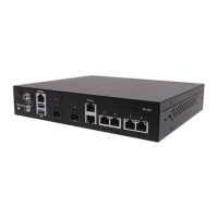
Lists the main features and capabilities of the NCA-5210 platform.

Package Content

Details the items included in the product package.

Ordering Information

Provides SKU numbers and corresponding main features for different product configurations.

Optional Accessories

System Specifications

Front Panel

Rear Panel

CHAPTER 2: MOTHERBOARD INFORMATION

Block Diagram

Illustrates the data flow and component connections on the motherboard.

Motherboard Layout

Jumper Setting and Connector Pin-Out

CMOS1: Clear CMOS setting

Details how to clear the CMOS settings using the CMOS1 jumper.

JSLRST1: Select RESET1 option

Explains the selection of reset options using the JSLRST1 jumper.

SSLOTA1, SSLOTA2: Determine whether to enable SLOT4 or SLOT5.

Describes how to enable or disable PCIe slots SLOT4 and SLOT5 using jumpers.

SPEG1: PCIe;PEG bus configuration

Outlines the PCIe/PEG bus configuration scenarios based on jumper settings.

Connector Pin Assignments

PWBT1: ATX Power ON switch

Lists pin assignments for the ATX Power ON switch connector.

ATX1: 8-pin Power Connector

Details the pin assignments for the 8-pin ATX power connector.

ATX2: 24-Pin ATX Power Connector

Provides pin assignments for the 24-pin ATX power connector.

JSPIROM1: SPIROM BIOS Programming pin header

JPMBUS1: Redundant PSU PMBUS Connector

JLCM1: 24-Pin LCM w;key Connector

JUSB1: USB 2.0 Port1;2 internal pin header

JCOM1: COM Port1 Console internal pin header

JLOM1: LOM port pin header

JDIO1: Digital I;O Connector (For LS only)

RESET1: RESET Pin Header

SATA1~SATA4: SATA 7-pin signal connectors

FAN1~4:5-Pin CPU FAN connectors

CASOPEN1: Case open detect Pin Header.

JTPM1: TPM (Trusted Computing) Module Pin Header.

JVGA1: 12-Pin VGA Connector (enabled from the IPMI card)

JCOM2: COM PORT 2 internal pin header

JUSB2: USB 2.0 Port3;4 pin header

OPMA1: OPMA Socket

MSATA1: mSATA socket for storage devices

JUSB3: 2 x USB3.0 ports pin header

J80 PORT1: 80 Port debug Connector (For Factory debug Only)

CHAPTER 3: HARDWARE SETUP

Opening the Chassis

Provides step-by-step instructions with images for opening the system chassis.

Installing the CPU, Heatsink and Fan Duct

Installing System Memory

Installing Disk Drives

Installing mSATA Module

Installing IPMI Card

Replacing Cooling Fans

Replacing NIC modules

Mounting the System

Attaching the Short Ear Brackets

Explains how to attach the short ear brackets to the system chassis.

Attaching the Slide Rail

Details the components of the slide rail kit and their basic structure.

Attaching Rail Brackets

Installing the Slide Rail Assemblies

Installing the Chassis onto the Rack

Explains how to stretch and lock the inner channels of the slide rails in preparation for chassis installation.

CHAPTER 4: BIOS SETUP

Instructions of BIOS navigations

Explains how to navigate the BIOS utility using keyboard keys and their functions.

Main

Advanced

Super IO Configuration

Allows configuration of Super IO chip parameters, including serial and parallel ports.

Parallel Port Configuration

HW Monitor

Serial Port Console Redirection

Console Redirection: select “Enabled” or “Disable” for COM port console redirection.

Explains how to enable or disable console redirection for COM ports.

Console Redirection Settings

Bits per second

Data Bits

Parity Bits

Stop Bits

Flow Control

VT-UTF8 Combo Key Support

Recorder Mode

Putty KeyPad

CPU Configuration

Hyper-threading

Enables or disables hyper-threading technology for improved performance on supported OS.

Active Processor Cores

Execute Disable Bit

SATA Configuration

SATA Mode Selection

Determines how SATA controllers operate (AHCI or RAID).

mSATA

SATA1

SATA2

SATA3

SATA4

USB Configuration

USB Devices

Displays information about connected USB devices.

Legacy USB Support

Enables or disables legacy USB support for compatibility.

LAN Boot Select

On Board LAN Boot

Configures the onboard LAN boot option, which defaults to disabled.

Chipset

System Agent (SA) Configuration

Configures system agent parameters.

VT-d

Enables or disables Intel VT-d virtualization function.

Memory Configuration

PCH-IO Configuration

Intel PCH RC Version

Intel PCH SKU Name

Intel PCH Rev ID

Restore On Power Loss

Security

Administrator Password

Sets an administrator password to restrict access to Setup.

User Password

Sets a user password for power-on and Setup access.

Boot

Boot mode select

Selects the boot mode between LEGACY and UEFI.

Boot Option #1

Boot Option #2

Boot Option #3

USB Device BBS Priorities

Boot Option #1

Boot Option #2

Boot Option #3

Boot Option #4

Save & Exit

Save Changes and Exit

Saves current configuration and exits the BIOS setup utility.

Discard Changes and Exit

Restore Defaults

Boot Override

APPENDIX A: PROGRAMMING WATCHDOG TIMER

APPENDIX B: SETTING UP CONSOLE REDIRECTION

APPENDIX C: PROGRAMMING GENERATION 3 LAN BYPASS

APPENDIX D: PROGRAMMING THE LCM

APPENDIX E: PEG PORT CONFIGURATION FOR ALTERNATIVE CPU

APPENDIX F: TERMS AND CONDITIONS

Warranty Policy

Details the terms and duration of the product warranty.

Requesting a RMA#

Instructs on the process of obtaining a Return Merchandise Authorization (RMA) number.

RMA Service Request Form

Lanner NCA-5210 Specifications

General IconGeneral
Form Factor1U Rackmount
USB Ports2 x USB 3.0
Operating Temperature0°C to 40°C (32°F to 104°F)
Storage1 x 2.5" SATA HDD/SSD
Power Supply250W
Operating SystemLinux, Windows
Expansion Slots1 x Mini-PCIe
Serial Ports1 x RJ-45 Console
Dimensions44mm

Related product manuals