25
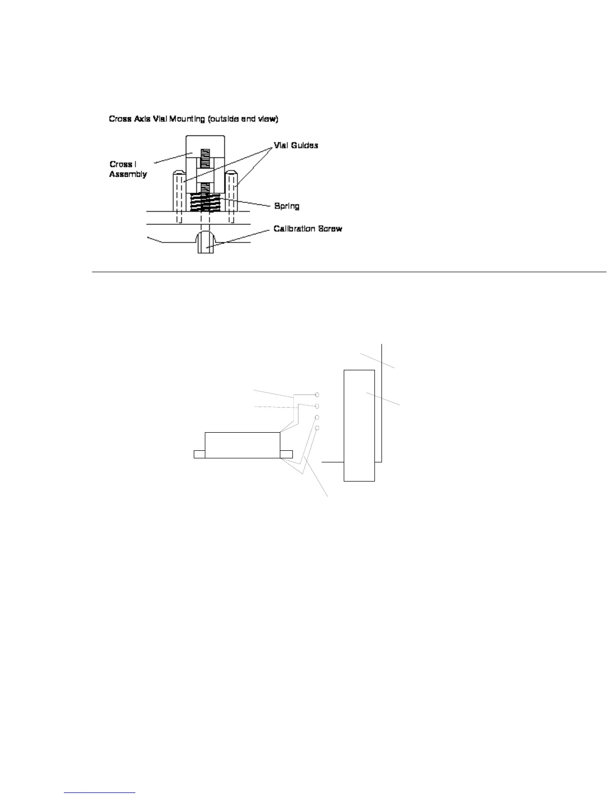
FIG. 7
Cross Sensor Mounting
FIG. 8 Cross Sensor Wiring
Cross Sensor
P. C. B .
Mount
Leads solder in from back or P.C.B.
Rear Lead
Front Lead
Black Marked Wire
A. Removal
1. Remove base plate assembly (refer to procedure #103).
2. Remove sensor leads from the circuit board (leads are soldered).
3. Using a Phillips driver, loosen the sensor guide screws.
4. Using a 1/4" socket driver, remove the x-axis calibration screw.
5. Using a broad tipped Phillips driver, remove the screw at pivot end of
sensor.
6. Lift the sensor off of the instrument plate. Note: pivot bearings are
under the sensor.
B. Replacement
1. Solder the sensor wires into the circuit board (refer to drawings above).
2. Place the sensor on the instrument plate.