26
a. Ensure both pivot bearings are in instrument plate, under pivot end of
sensor.
b. Position the tension spring under the calibration end of the sensor.
3. Insert the 8-32 Phillips head screw with washers into pivot end (refer to
drawing).
a. Tighten the screw until bottomed out and back off 1/8 turn.
4. Insert the x-axis calibration screw through the instrument plate and
tension spring.
a. Thread the cal. screw into the brass calibration bar until approximately
1/4 inch of it is through.
5. Push the sensor standoffs against the sensor assembly and tighten the
guide screws.
6. Replace base plate assembly (see procedure #104)
7. Adjust the cross axis grade alarm dead band (see procedure #108)
#107 Circuit Board Removal and Replacement
Tools required: Grounded soldering iron Time:
.5
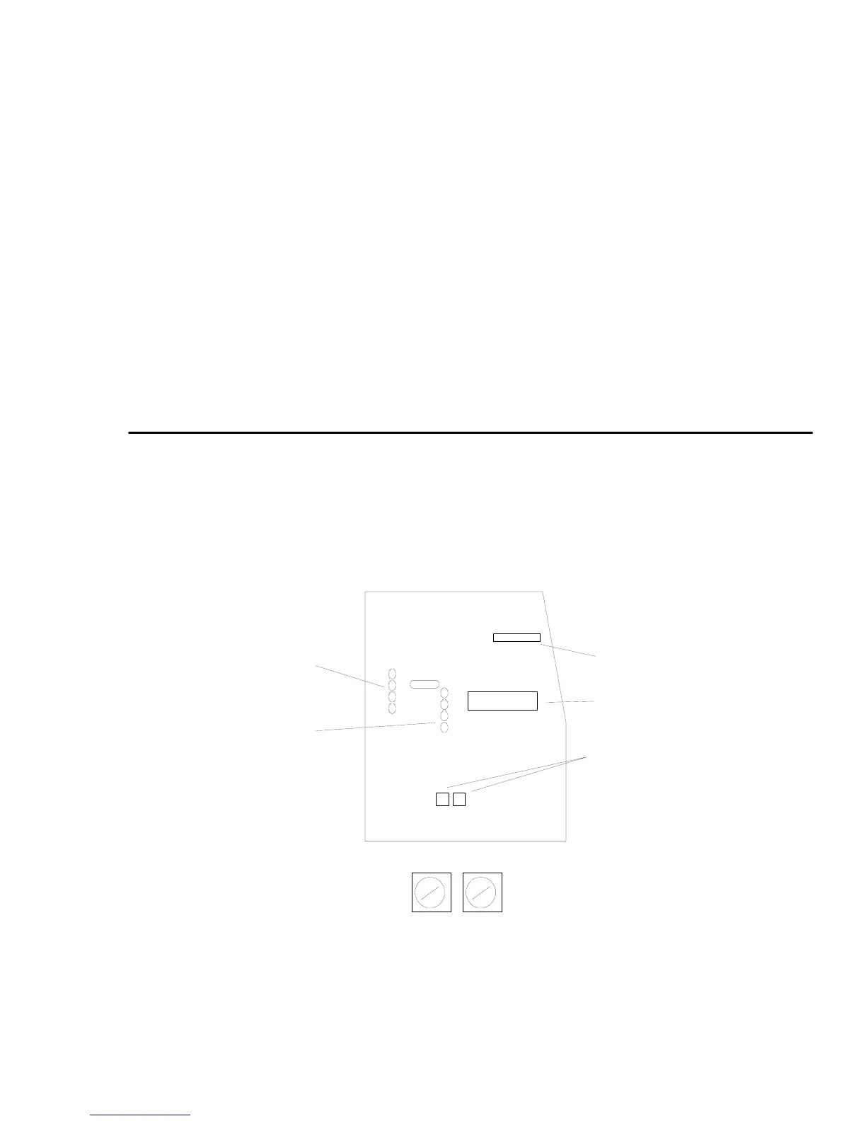
FIG. 9 Circuit Board Connections and Adjustments
Connections for
Slope Sensor
Connections for
Cross Sensor
Laser Power Pot.
Grade Alarm Pots.
Microprocessor
Grade Alarm Potentiometers
S-Axis
X-Axis
Clockwise adjustment
makes deadband
smaller