37
L1-S Board Update Info
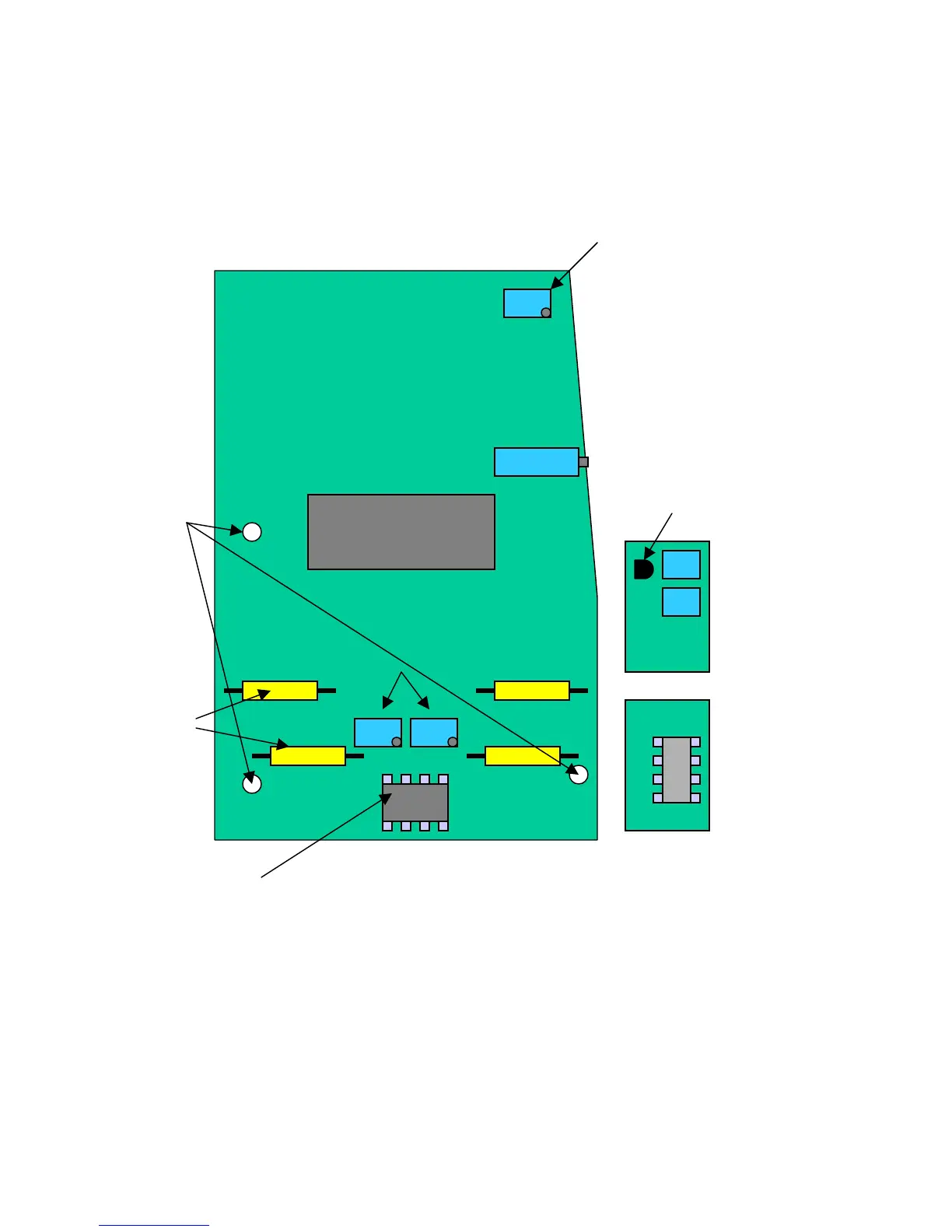
Add low battery
threshold
adjustment pot, 10-
2645, across R24 if
the threshold is
lower than 4.45V, in
“OFF” mode. Clip
one of the outer
leads and solder the
other leads across
R24.
Replace deadband adjustment
pots, 10-2645, if not blue or
yellow 500K pots
Replace
capacitors,
10-2060, (4)
if marked
with “IC”
and batch
“H-27”
Replace if it has the
“Phillips” logo and
the customer has
complained of
unstable calibration.
If there is a “spin-up” routine upon start-up
and there is a piggyback board installed
then the “spin-up” function should be
disabled and a new type of motor(gold
body) installed.
Clip out
I.C. to
disable
spin-up
Clip out Q1 to
disable spin-up
Newer boards
must have
insulators
between screw
heads and board