29
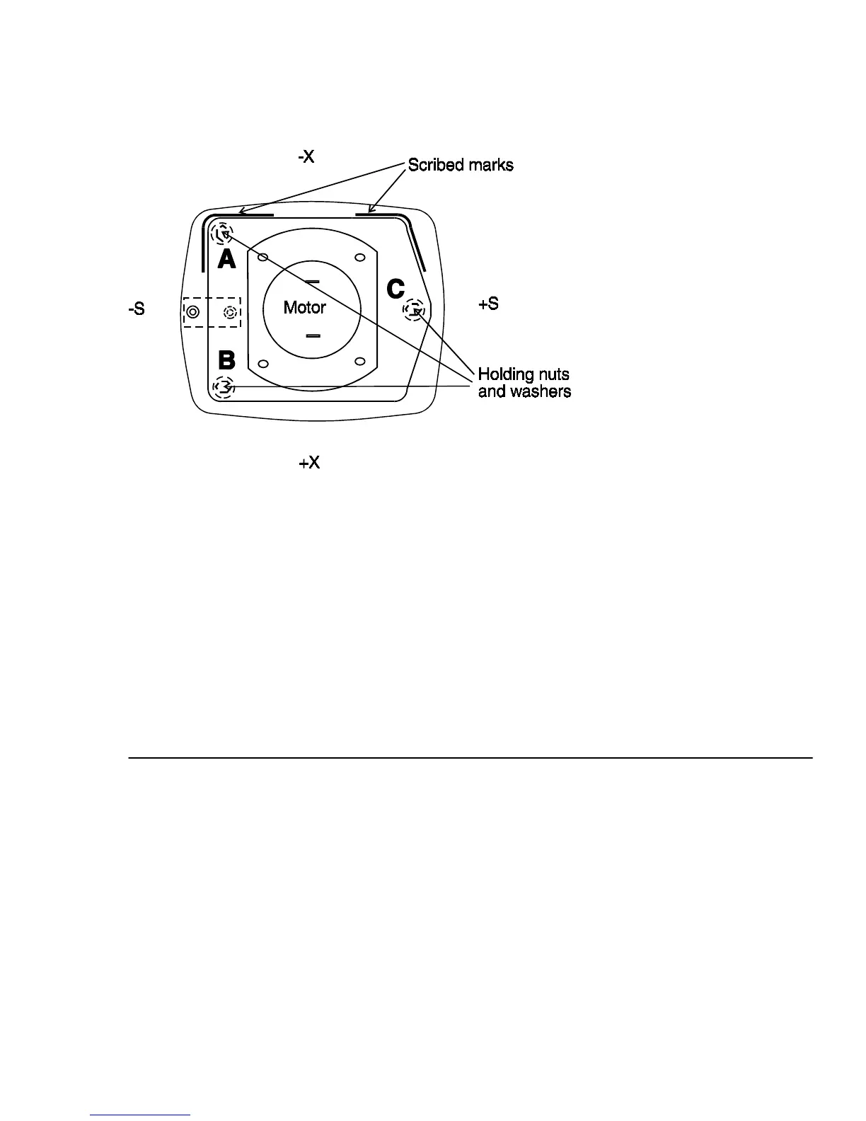
FIG. 9 Motor Mounting and Adjustment points
8. Scribe a mark around the motor mounting plate (this is to ensure proper
centering when installing the new motor assembly).
9. Remove the three holding nuts and washers.
10. Remove the motor assembly.
B. Replacement (does not apply to L1-S)
1. Position the motor assembly in alignment with scribe marks made in
step A8.
2. Replace and tighten the holding nuts and washers.
3. Solder the motor wires to the motor terminals.
4. Check squaring (refer to procedure #110).