RED WIRE: connect to positive 12V.
BLACK WIRE: -BROWN wire of the unit.connect to the BLUE
RED WIRE ROSSO: connect to positive 12V.
BLACK WIRE: connect to GND
BLUE WIRE: connect to -BROWN wire of the unit.the BLUE
GREY WIRE: connect to the EY wire of the unitGR
SENSITIVITY ADJUSTMENT
3-WAY CONNECTOR
FROM MAIN UNIT
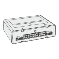
LED/ELECTONIC KEY SOCKET
connect the white and red connectors of the electronic socket to the respective
connectors coming from the alarm centre.
CONNECTIONS DIAGRAM FOR SIREN 909 TF
CONNECTIONS DIAGRAM Sl FOR SELF-POWERED SIREN 919
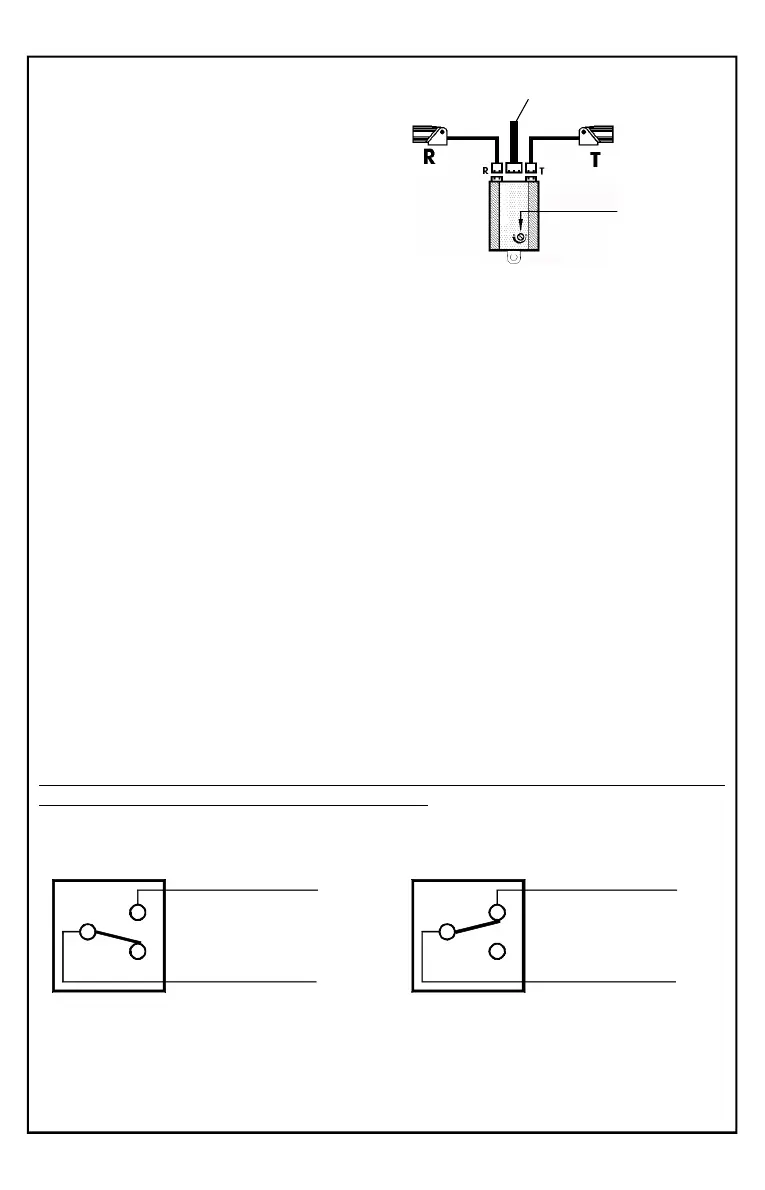
ULTRASONIC SENSOR MODULE:
Insert the RED connector coming from the
capsule to the T connector of the module and
the WHITE connector to the R connector.
Insert the 3-pin white connector coming from
the alarm directly into the module.
Do not shorten or lengthen the sensor
wires.
Accessories connections and relè operation mode
Built-in Relè
When the alarm is triggered, the two wires and are YELLOW-GREEN GREEN
disconnected (open contact), preventing the vehicle from starting.
The contact will only closed when, with the alarm is disarmed and you turn the
ignition key to ON, allowing the vehicle to start.
System
ARMED or ALARM TRIGGERED
30
87
YELLOW/GREEN
GREEN
30
87
YELLOW/GREEN
GREEN
System
DIS + ACC ON ARMED
Starting BLOCKED
Starting ALLOWED
Pag.18
NOTA: The relay can be programmed to drive an additional siren.
See page 25 Functions 9 and 13.