Page 23
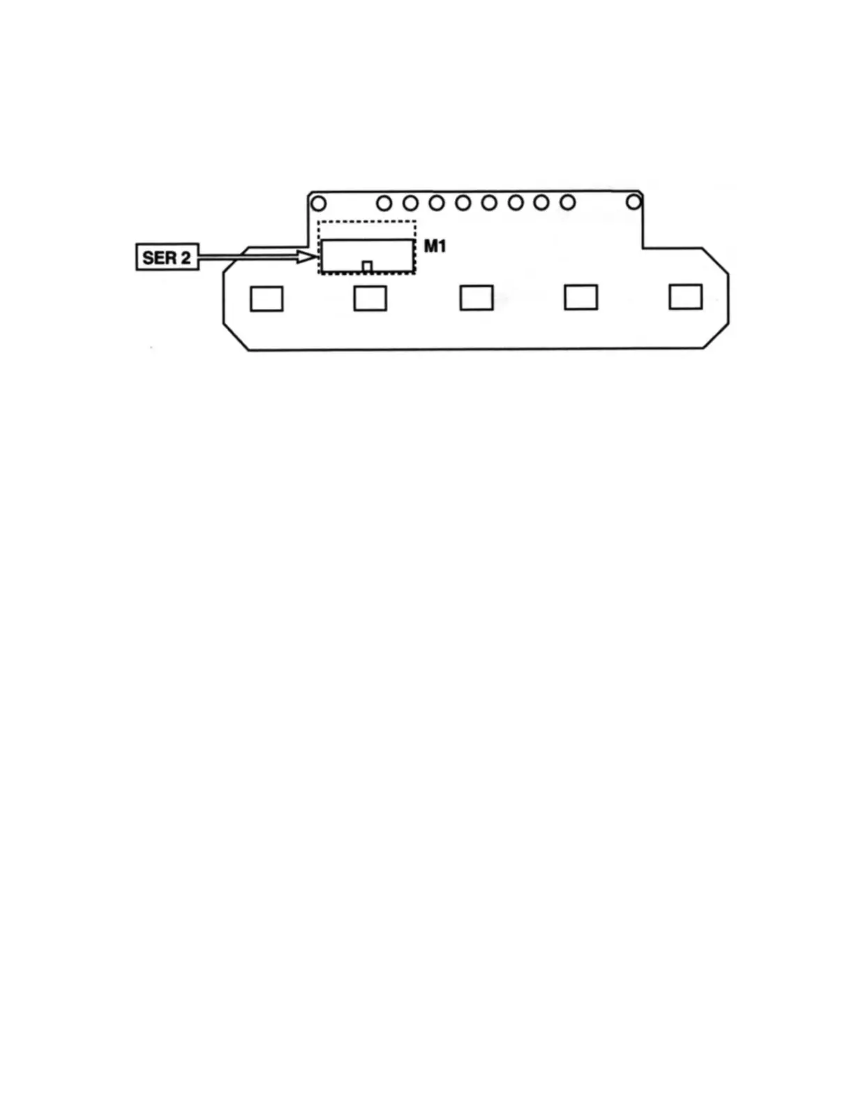
6.4 Control Panel Connection Diagram
6.5 Wiring Diagram Definitions
EV GR Coffee brewing group solenoid valve
EV H Hot water delivery solenoid valve
EV AL Automatic refill system solenoid valve
T1 Connection on control board of the triac that feeds the boiler heating element
T2 Connection on control board of the triac that feeds the group heating element
P1 Connection of the control board on the triac that feeds the boiler heating
element
P2 Connection of the control board on the triac that feeds the group heating
element
SER 1 Connection control panel on control board
SER 2 Connection control board on control panel
F Flow meter
F1 in Phase inlet into the triac that feeds the boiler heating element
F1 out Phase outlet from the triac that feeds the boiler heating element
F2 in Phase inlet into the triac that feeds the group heating element
F2 out Phase outlet from the triac that feeds the group heating element
S1 Boiler temperature probe
S2 Brewing group temperature probe
SL Container water level sensor
SB Boiler Water Level Control
Display Cable Connector for Optional Timer Module
V Ventilator connection (steam boiler triac cooling fan)
P Vibe Pump
RC Heating element brewing group
TSC Safety thermostat for brewing group heating element
RB Boiler heating element
TSB Safety thermostat for boiler heating element
JP4 15/20A Mode Selector Connection
JP3 Optional Timer Switch Connector
SD Optional Timer On/Off Switch
SE 15/20A Mode Switch