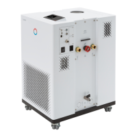
Table 1 Unit IN 130 T IN 230 T IN 230 TW IN 530 T
‑ Right mm 500 500 200 500
‑ Left mm 500 500 200 500
Table 2 Unit IN 530 TW IN 1030 T IN 1330 TW IN 1830 TW
ACC area À
°C -30 – 120 -30 – 150 -30 – 150 -30 – 150
Temperature stability Á
K
±0.05 ±0.1 ±0.1 ±0.1
Device dimensions
width x depth x height
mm
560 x 550 x
1325
760 x 650 x
1605
760 x 650 x
1605
760 x 650 x
1605
Filling volume
‑ minimum L 7.2 9.7 9.7 9.7
‑ maximum L 20.5 25.5 25.5 25.5
Pump data 50 Hz
‑ maximum discharge pres-
sure
bar 3.5 5.5 5.5 5.5
‑ Maximum flow rate l/min 40.0 60.0 60.0 60.0
Pump data 60 Hz
‑ maximum discharge pres-
sure
bar 4.6 7.0 7.0 7.0
‑ Maximum flow rate l/min 45 70.0 70.0 70.0
Connector thread (outer)
inlet/outlet
inch / mm
G¾"
M38 x 1.5 M38 x 1.5 M38 x 1.5
Noise level 50 Hz Â
dB(A) 62 69 59 64
Noise level 60 Hz Â
dB(A) 64 70 62 67
Weight kg 149.5 222.5 225.0 231.0
Distance between device and
environment
‑ Front mm 200 500 200 200
‑ Back mm 200 500 200 200
‑ Right mm 200 500 200 200
‑ Left mm 200 500 200 200
À - ACC area (Active Cooling Control) according to DIN 12876 is the
working temperature range during operation with an active cooling unit.
Á - Temperature stability determined according to standard DIN 12876-2
 - Noise level determined according to standard EN 11201 for operating
position in front of the device at 1 meter distance
V6 Integral Process Thermostats and High-Temperature Thermostats 163 / 198
 Loading...
