36
THROTTLE AND STARTER SYSTEM
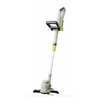
■ Check the PCB assembly, microswitch, throttle safety and throttle lever. Replace if required (Fig.
64).
Throttle
Safety
Microswitch
Throttle
Lever
Fig. 64
PCB
Assembly
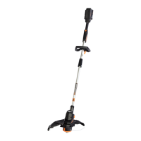
■ Use a proper tool (e.g. a screwdriver) to pry off the microswitch.
■ Open the corrugated pipe buckle and disconnect the male and female terminals of the motor drive
lines (blue). Remove the motor drive lines of the handle part from the corrugated pipe. Remove the
PCB assembly by pulling it out of its slot (Fig. 65 & 66).
Microswitch Wiring
Harness
Motor Drive
Lines of
Handle
Fig. 65 Fig. 66
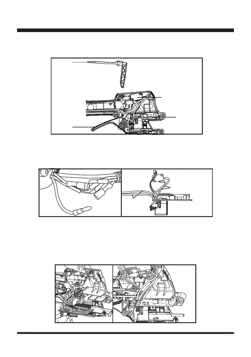
■ Replace with a new PCB assembly and microswitch.
■ Pass the motor drive lines of the handle part through the corrugated pipe, and connect with the
motor drive lines of the engine part.
■ Restore the motor drive lines of the handle part, the wiring harness of the microswitch, and the LED
cable into the slot as circled in Fig. 67. Align and re-insert the PCB assembly into the slot. Make
sure it is installed into place (Fig. 67 & 68).
Fig. 67 Fig. 68

 Loading...